


Interface Cards are circuit boards that contain the electronics needed to tie a peripheral to your application hardware. Accessories are circuit boards or other hardware that make building your application hardware easier. Accessories include power distribution cards, mounting hardware, and prototyping card.
THE CARDS SHOWN BELOW ARE NO LONGER IN PRODUCTION. However the schematics are given on their respective pages and the schematics are released under Creative Commons so you can build or copy these cards if you wish.
QUICK INDEX: Controller Cards User Interface Cards Motion Control Cards General Purpose I/O Cards Accessories Card Dimensions Card Electrical Interface
 Baseboard:
The FPGA-based Baseboard gives you the ability to run nine different
peripherals simultaneously. Every peripheral has Linux support making
it easy to build a complete robotic or automation system. Click
here for more information.
Baseboard:
The FPGA-based Baseboard gives you the ability to run nine different
peripherals simultaneously. Every peripheral has Linux support making
it easy to build a complete robotic or automation system. Click
here for more information.
 AVR MEGA Microcontroller Card:
The MEGA card has a MEGA88PB AVR microprocessor with eighteen available
IO pins. From the Linux host you can read and write the AVR program flash,
read and write the EEPROM, read and write the AVR hardware registers, and
read and write predefined RAM locations. The predefined RAM locations
act as host visible registers in your AVR program.
Click here for more information.
AVR MEGA Microcontroller Card:
The MEGA card has a MEGA88PB AVR microprocessor with eighteen available
IO pins. From the Linux host you can read and write the AVR program flash,
read and write the EEPROM, read and write the AVR hardware registers, and
read and write predefined RAM locations. The predefined RAM locations
act as host visible registers in your AVR program.
Click here for more information.
User Interface
 Audio Amplifier Card
:
The Audio Amplifier Card uses a Diodes PAM8408 two Watt stereo,
Class-D audio amplifier chip. The card has rugged screw terminals
for power and has a 3.5mm jack for external input. An eight pin
connector provides a way to connect to an FPGA for volume control,
mute, and an LED indicator.
Click here for more information.
Audio Amplifier Card
:
The Audio Amplifier Card uses a Diodes PAM8408 two Watt stereo,
Class-D audio amplifier chip. The card has rugged screw terminals
for power and has a 3.5mm jack for external input. An eight pin
connector provides a way to connect to an FPGA for volume control,
mute, and an LED indicator.
Click here for more information.
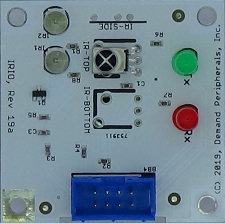 IR Receiver/transmitter
The IR Input/Output card provides consumer IR input and output
ot your robot or automation. The card requires one slot on the FPGA
card and must be paired with the "irio" FPGA peripheral. Linux
support includes both TCP and command line control of the card.
Input from the card is event driven so your code does not need
to poll for switch transitions.
Click here for more information.
IR Receiver/transmitter
The IR Input/Output card provides consumer IR input and output
ot your robot or automation. The card requires one slot on the FPGA
card and must be paired with the "irio" FPGA peripheral. Linux
support includes both TCP and command line control of the card.
Input from the card is event driven so your code does not need
to poll for switch transitions.
Click here for more information.
 Six Digit LCD Display
The six digit LCD display provides a large, easy to read, display
of six seven-segment digits. The card requires on slot on the FPGA
card and must be paired with the "lcd6" FPGA peripheral. Linux
support includes both TCP and command line control of the both the
digits and even the individual segments on the display.
Click here for more information.
Six Digit LCD Display
The six digit LCD display provides a large, easy to read, display
of six seven-segment digits. The card requires on slot on the FPGA
card and must be paired with the "lcd6" FPGA peripheral. Linux
support includes both TCP and command line control of the both the
digits and even the individual segments on the display.
Click here for more information.
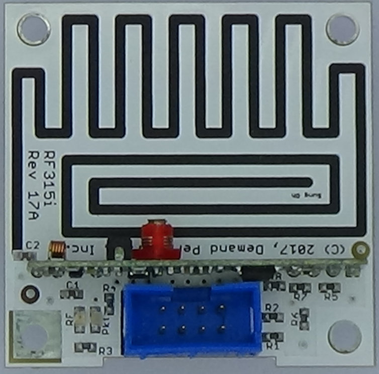 Keyfob RF Receiver
The keyfob receiver card receives and decodes most 315 MHz and
434 MHz remote controls. One model has an a built-in antenna
for 315 MHz and the other model has an SMA connector for either
315 or 434 MHz. The card requires one slot on the FPGA card
and must be paired with the "rfob" FPGA peripheral. Input from
the card is event driven so your code does not need to poll for
switch transitions.
Click here for more information.
Keyfob RF Receiver
The keyfob receiver card receives and decodes most 315 MHz and
434 MHz remote controls. One model has an a built-in antenna
for 315 MHz and the other model has an SMA connector for either
315 or 434 MHz. The card requires one slot on the FPGA card
and must be paired with the "rfob" FPGA peripheral. Input from
the card is event driven so your code does not need to poll for
switch transitions.
Click here for more information.
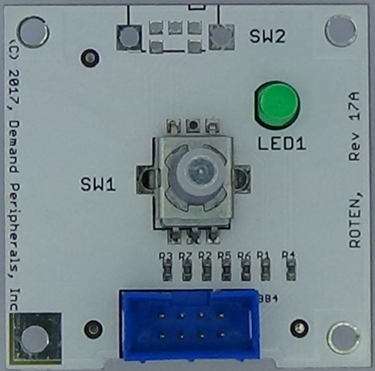 Rotary Encoder
The Rotary Encoder Card provides a continuous rotation encoder
with built-in push button and an indicator LED.
Using a DPI FPGA card gives Linux support that includes both
TCP and a command line interface to the card. Input from the
card is event driven so your code does not need to poll for
switch transitions.
Click here for more information.
Rotary Encoder
The Rotary Encoder Card provides a continuous rotation encoder
with built-in push button and an indicator LED.
Using a DPI FPGA card gives Linux support that includes both
TCP and a command line interface to the card. Input from the
card is event driven so your code does not need to poll for
switch transitions.
Click here for more information.
 Quad Switch Card
The Quad Switch Card provides four attractive slide switches
for input to your robot or automation. The card can use
GPIO pins from an Arduino or Raspberry Pi, or can use
an FPGA slot paired to the "in4" FPGA peripheral.
Quad Switch Card
The Quad Switch Card provides four attractive slide switches
for input to your robot or automation. The card can use
GPIO pins from an Arduino or Raspberry Pi, or can use
an FPGA slot paired to the "in4" FPGA peripheral.
Using a DPI FPGA card gives Linux support includes both TCP
and a command line interface to the switch state. Input
from the card is event driven so your code does not need to
poll for switch transitions.
Click here for more information.
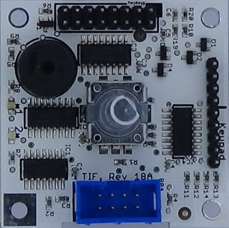 Text Interface Card
The Text Interface Card provides several of the most common user
interface elements. Included are an interface to text display,
a piezo beeper, a rotary encoder with push button, an interface
to a 4x5 keypad, and two LEDs. The card requires one slot on
the FPGA card and is paired with the "tif" FPGA peripheral.
Linux support includes both TCP and a command line interface.
Input from the card is event driven so your code does not need
to poll for switch transitions.
Click here for more information.
Text Interface Card
The Text Interface Card provides several of the most common user
interface elements. Included are an interface to text display,
a piezo beeper, a rotary encoder with push button, an interface
to a 4x5 keypad, and two LEDs. The card requires one slot on
the FPGA card and is paired with the "tif" FPGA peripheral.
Linux support includes both TCP and a command line interface.
Input from the card is event driven so your code does not need
to poll for switch transitions.
Click here for more information.
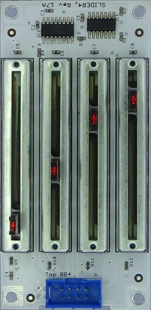 Quad Slide Pot
The Quad Slide Potentiometer Card provides four slide pots with a
10 bit ADC on each pot. The tip of each pot is illuminated with a
red LED making the pots easy to see in dim lighting. The card
requires one slot on the FPGA card and is paired with the "slider4"
FPGA peripheral. Input from the card is event driven so your code
does not need to poll for switch transitions.
Click here for more information.
Quad Slide Pot
The Quad Slide Potentiometer Card provides four slide pots with a
10 bit ADC on each pot. The tip of each pot is illuminated with a
red LED making the pots easy to see in dim lighting. The card
requires one slot on the FPGA card and is paired with the "slider4"
FPGA peripheral. Input from the card is event driven so your code
does not need to poll for switch transitions.
Click here for more information.
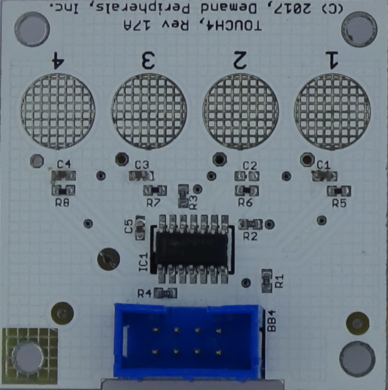 Quad Touch Interface
The Quad Touch Interface card provides four channel of touch input.
Touch pads are on the card and solder pads allow the addition of
external touch pads.
The card requires one slot on the FPGA card and is paired with the
"touch4" FPGA peripheral. Input from the card is event driven so
your code does not need to poll for switch transitions.
Click here for more information.
Quad Touch Interface
The Quad Touch Interface card provides four channel of touch input.
Touch pads are on the card and solder pads allow the addition of
external touch pads.
The card requires one slot on the FPGA card and is paired with the
"touch4" FPGA peripheral. Input from the card is event driven so
your code does not need to poll for switch transitions.
Click here for more information.
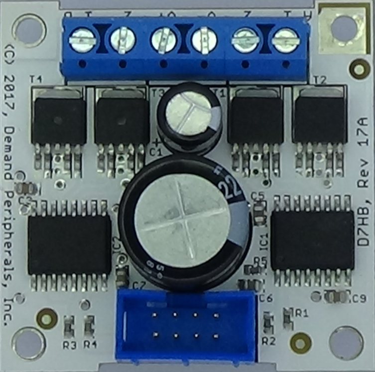 Dual 7-amp H-bridge
The Dual 7 Amp h-Bridge Card supports a continuous current of
7 Amps and a peak current of 12. Each H-Bridge uses two control
lines and has forward, reverse, brake, and coast modes of
operation. The Dual H-Bridge does not need the FPGA but is
often paired with either the dual DC motor controller (dc2)
peripheral or the bipolar stepper motor controller (stepb)
peripheral.
Click here for more information.
Dual 7-amp H-bridge
The Dual 7 Amp h-Bridge Card supports a continuous current of
7 Amps and a peak current of 12. Each H-Bridge uses two control
lines and has forward, reverse, brake, and coast modes of
operation. The Dual H-Bridge does not need the FPGA but is
often paired with either the dual DC motor controller (dc2)
peripheral or the bipolar stepper motor controller (stepb)
peripheral.
Click here for more information.
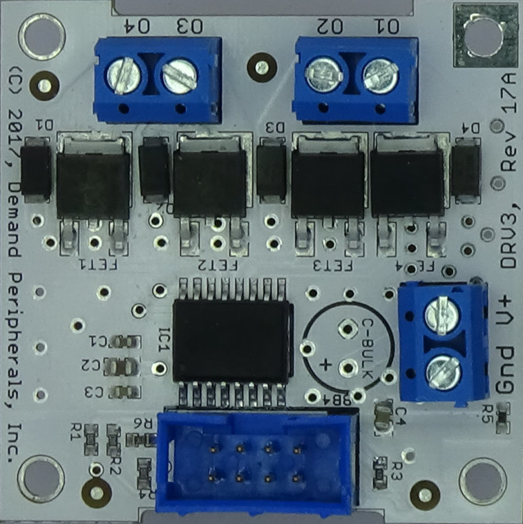 Quad Open Drain Driver
The Quad Open Drain Driver Card provides four open-drain N-FETs.
Combined current on all FETs is limited to 15 Amps. The open
drain driver does not need the FPGA but is often paired with
either the "out4" peripheral or the unipolar stepper motor
controller ("stepu") FPGA peripheral.
Click here for more information.
Quad Open Drain Driver
The Quad Open Drain Driver Card provides four open-drain N-FETs.
Combined current on all FETs is limited to 15 Amps. The open
drain driver does not need the FPGA but is often paired with
either the "out4" peripheral or the unipolar stepper motor
controller ("stepu") FPGA peripheral.
Click here for more information.
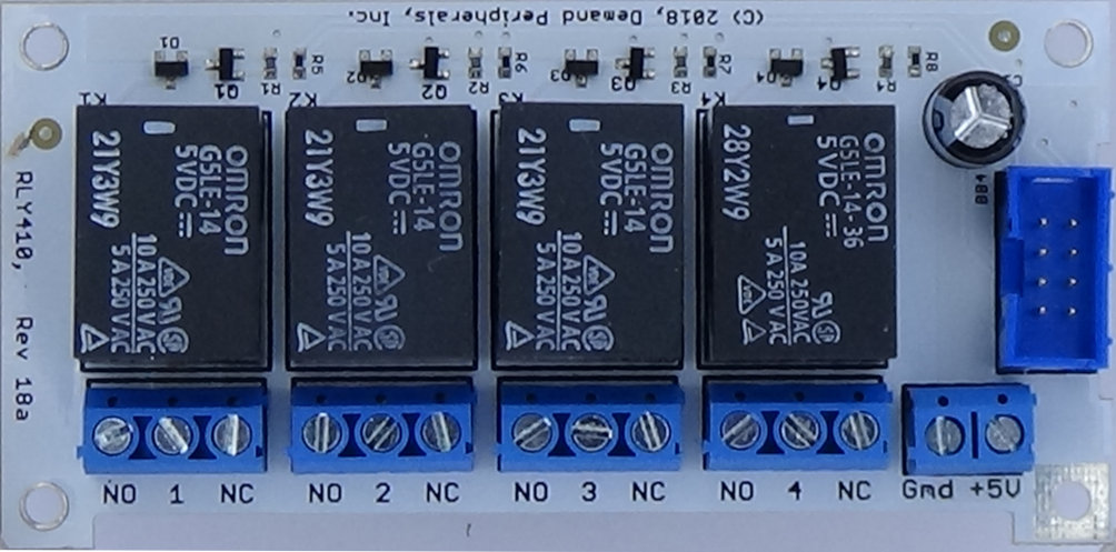 Quad 8 Amp Relay Card :
The Quad 8 Amp Relay Card has four individually controlled Class B
SPDT relays. Each relay has a discrete driver and a back EMF
diode. The coil voltage is five volts, making the card compatible
with the rest of your system.
Click here for more information.
Quad 8 Amp Relay Card :
The Quad 8 Amp Relay Card has four individually controlled Class B
SPDT relays. Each relay has a discrete driver and a back EMF
diode. The coil voltage is five volts, making the card compatible
with the rest of your system.
Click here for more information.
 Quad Digital Pot
The Quad Digital Potentiometer uses the MCP4251 to provide four
computer controlled 10 KOhm potentiometers with 257 steps. Other
values are available on request. The card uses one slot on the
FPGA card and must be paired with the "qpot" FPGA peripheral.
Click here for more information.
Quad Digital Pot
The Quad Digital Potentiometer uses the MCP4251 to provide four
computer controlled 10 KOhm potentiometers with 257 steps. Other
values are available on request. The card uses one slot on the
FPGA card and must be paired with the "qpot" FPGA peripheral.
Click here for more information.
CARD DIMENSIONS:
CARD ELECTRICAL INTERFACE:
Slot #1 always refers to the three buttons and eight LEDs on the
Baseboard. Slot #10 refers to the three 3-pin headers on the Baseboard.
These 3-pin headers can be used as GPIO lines or for three Ping))) (tm)
ultrasonic distance sensors.
Note that the four connectors on the Baseboard4 are each split into two
eight pin cables. Each of these 8-pin cables out to the interface cards
has four FPGA lines, two ground lines, a 3.3 volt line, and a 5 volt line.
The lines are arranged as follows:
The FPGA is not five volt tolerant. Applying more that 3.3 volts
to the FPGA pins will damage the FPGA.
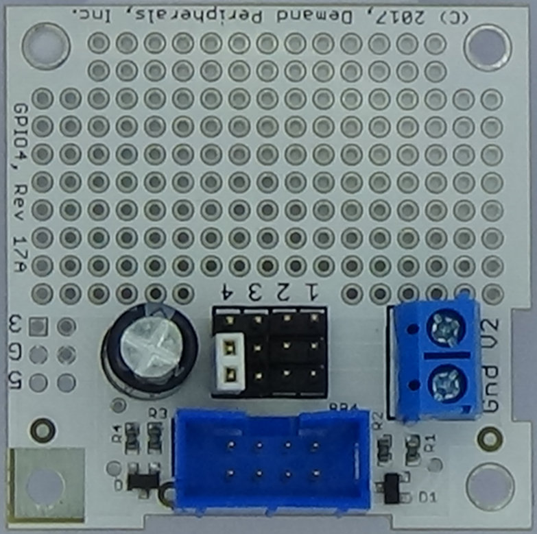 Quad GPIO
The Quad General Purpose Input/Output Card provides four connections
to the FPGA. The output is 3.3 volts and the input can range
between 3.3 and 5 volts. This card is often paired with the
"gpio4", "in4", or the "out4" FPGA peripherals. The GPIO4 card
is also used with the dual quadrature decoder ("quad2"), the quad
event counter ("count4"), the quad PWM input ("pwmin4"), the quad
PWM output ("pwmout4"), the quad Ping sensor interface ("ping4"),
and the quad servo controller ("servo4") FPGA peripherals.
Click here for more information.
Quad GPIO
The Quad General Purpose Input/Output Card provides four connections
to the FPGA. The output is 3.3 volts and the input can range
between 3.3 and 5 volts. This card is often paired with the
"gpio4", "in4", or the "out4" FPGA peripherals. The GPIO4 card
is also used with the dual quadrature decoder ("quad2"), the quad
event counter ("count4"), the quad PWM input ("pwmin4"), the quad
PWM output ("pwmout4"), the quad Ping sensor interface ("ping4"),
and the quad servo controller ("servo4") FPGA peripherals.
Click here for more information.
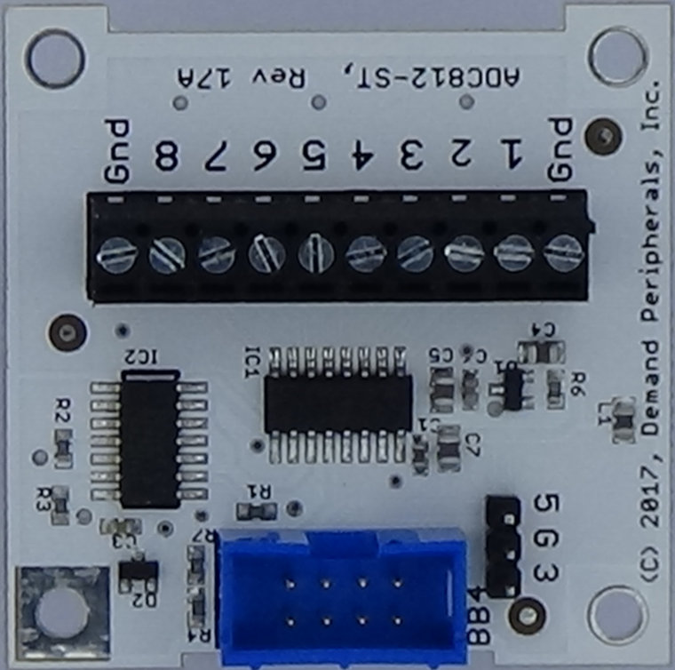 Octal 12-bit ADC
The Octal 12 Analog-to-Digital Converter Card uses the Microchip
MCP3304 to provide eight channels of analog input. The card uses
one slot on the FPGA card and must be paired with the "adc812"
FPGA peripheral. Linux support includes both TCP and a command
line interface to the card. Input from the card is event driven
so your code does not need to poll for ADC readings.
Click here for more information.
Octal 12-bit ADC
The Octal 12 Analog-to-Digital Converter Card uses the Microchip
MCP3304 to provide eight channels of analog input. The card uses
one slot on the FPGA card and must be paired with the "adc812"
FPGA peripheral. Linux support includes both TCP and a command
line interface to the card. Input from the card is event driven
so your code does not need to poll for ADC readings.
Click here for more information.
 Octal SRF04 Interface
The Octal Ultrasonic Distance Interface Card drives up to eight
SRF04 distance sensors. The card requires one slot on the FPGA
card and must be paired with the "us8" FPGA peripheral. Linux
support includes both TCP and command line control of the card.
Input from the card is event driven so your code does not need
to poll for readings.
Click here for more information.
Octal SRF04 Interface
The Octal Ultrasonic Distance Interface Card drives up to eight
SRF04 distance sensors. The card requires one slot on the FPGA
card and must be paired with the "us8" FPGA peripheral. Linux
support includes both TCP and command line control of the card.
Input from the card is event driven so your code does not need
to poll for readings.
Click here for more information.
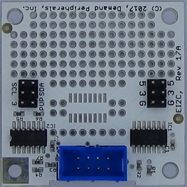 I2C Prototyping Card
The I2C Prototyping Card provides an easy way to connect
almost any I2C device to your robot or automation. The card
requires a slot on the FPGA card and must be paired with the
"ei2c" FPGA peripheral.
Click here for more information.
I2C Prototyping Card
The I2C Prototyping Card provides an easy way to connect
almost any I2C device to your robot or automation. The card
requires a slot on the FPGA card and must be paired with the
"ei2c" FPGA peripheral.
Click here for more information.
 SPI Prototyping Card
The SPI Prototyping Card provides an easy way to connect
almost any SPI device to your robot or automation. The card
requires a slot on the FPGA card and must be paired with the
"espi" FPGA peripheral. Linux support includes both TCP and
a command line interface.
Click here for more information.
SPI Prototyping Card
The SPI Prototyping Card provides an easy way to connect
almost any SPI device to your robot or automation. The card
requires a slot on the FPGA card and must be paired with the
"espi" FPGA peripheral. Linux support includes both TCP and
a command line interface.
Click here for more information.
 USB 2.0 Hub:
The four port USB 2.0 HUB4 card has mounting holes for secure placement,
per-port power control, a reliable screw terminal for input power, and
the ability to pass power up to the host if needed.
Click here for more information.
USB 2.0 Hub:
The four port USB 2.0 HUB4 card has mounting holes for secure placement,
per-port power control, a reliable screw terminal for input power, and
the ability to pass power up to the host if needed.
Click here for more information.
 Real Time Clock
The Real-Time Clock Card uses a PCF2123 RTC chip and coin cell
to give up to a year of battery backed date and time. The
PCF2123 has an alarm output that you can configure to go low
at a set time. The alarm output can control the remote input
on either of the Power Distribution Cards.
Click here for more information.
Real Time Clock
The Real-Time Clock Card uses a PCF2123 RTC chip and coin cell
to give up to a year of battery backed date and time. The
PCF2123 has an alarm output that you can configure to go low
at a set time. The alarm output can control the remote input
on either of the Power Distribution Cards.
Click here for more information.
 Octal Input/Output
The Octal Input/Output Card provides eight binary outputs and
eight binary inputs. Linux support includes both TCP and
command line control of the card. Input from the card is event
driven so your code does not need to poll for input transitions.
Click here for more information.
Octal Input/Output
The Octal Input/Output Card provides eight binary outputs and
eight binary inputs. Linux support includes both TCP and
command line control of the card. Input from the card is event
driven so your code does not need to poll for input transitions.
Click here for more information.
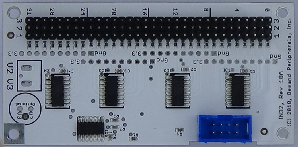 32 Channel Input
The 32 Channel Binary Input Card provides 32 bits of 5
Volt tolerant input. The inputs are on pin 1 of a 3-pin header.
The voltages at pins 2 and 3 are user selectable via screw terminals.
Linux support includes both TCP and command line control of the card.
Input from the card is event driven so your code does not need to
poll for input transitions. Click here
for more information.
32 Channel Input
The 32 Channel Binary Input Card provides 32 bits of 5
Volt tolerant input. The inputs are on pin 1 of a 3-pin header.
The voltages at pins 2 and 3 are user selectable via screw terminals.
Linux support includes both TCP and command line control of the card.
Input from the card is event driven so your code does not need to
poll for input transitions. Click here
for more information. 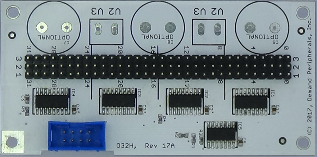 32 Channel Output
Card The 32 Channel Output Card provides thirty-two
3.3 Volt binary outputs. The inputs are on pin 1 of a 3-pin header.
The voltages at pins 2 and 3 are user selectable via screw terminals.
Linux support includes both TCP and command line control of the card.
Click here for more information.
32 Channel Output
Card The 32 Channel Output Card provides thirty-two
3.3 Volt binary outputs. The inputs are on pin 1 of a 3-pin header.
The voltages at pins 2 and 3 are user selectable via screw terminals.
Linux support includes both TCP and command line control of the card.
Click here for more information.
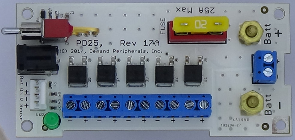 25 Amp Power Distribution Card :
The PD25 Power Distribution Card provides an easy way to control power
for your robot or automation. It can handle up to 25 Amps at 48 volts
and has an automotive style fuse for over-current protection. There
is a 5.5 mm barrel connector to attach your battery charger and the card
has a remote-on connector if you want to control the power from another
switch or a real-time-clock card.
Click here for more information.
25 Amp Power Distribution Card :
The PD25 Power Distribution Card provides an easy way to control power
for your robot or automation. It can handle up to 25 Amps at 48 volts
and has an automotive style fuse for over-current protection. There
is a 5.5 mm barrel connector to attach your battery charger and the card
has a remote-on connector if you want to control the power from another
switch or a real-time-clock card.
Click here for more information.
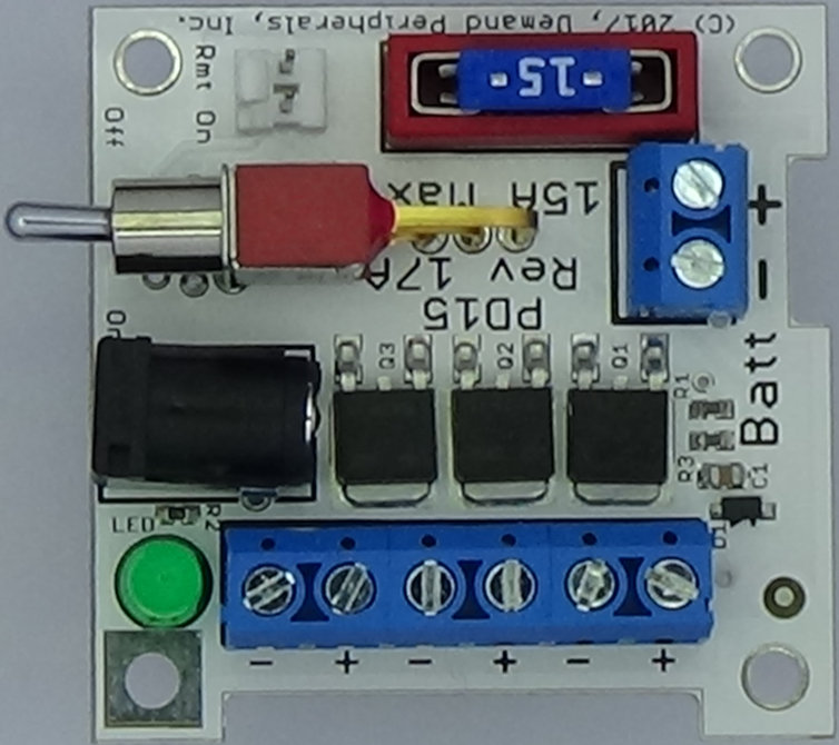 15 Amp Power Distribution Card :
The PD15 Power Distribution Card provides an easy way to control power
for your smaller robot or automation. It can handle up to 15 Amps at 48 volts
and has an automotive style fuse for over-current protection. There
is a 5.5 mm barrel connector to attach your battery charger and the card
has a remote-on connector if you want to control the power from another
switch or a real-time-clock card.
Click here for more information.
15 Amp Power Distribution Card :
The PD15 Power Distribution Card provides an easy way to control power
for your smaller robot or automation. It can handle up to 15 Amps at 48 volts
and has an automotive style fuse for over-current protection. There
is a 5.5 mm barrel connector to attach your battery charger and the card
has a remote-on connector if you want to control the power from another
switch or a real-time-clock card.
Click here for more information.
 5 Volt, 3 Amp Switching Regulator :
The 5 Volt Switch-Mode Regulator (SMR5) offers a 5 Volt output with
3 Amps of continuous current (4 Amps peak). It has low ripple,
reverse polarity protection, and high efficiency.
Click here for more information.
5 Volt, 3 Amp Switching Regulator :
The 5 Volt Switch-Mode Regulator (SMR5) offers a 5 Volt output with
3 Amps of continuous current (4 Amps peak). It has low ripple,
reverse polarity protection, and high efficiency.
Click here for more information.
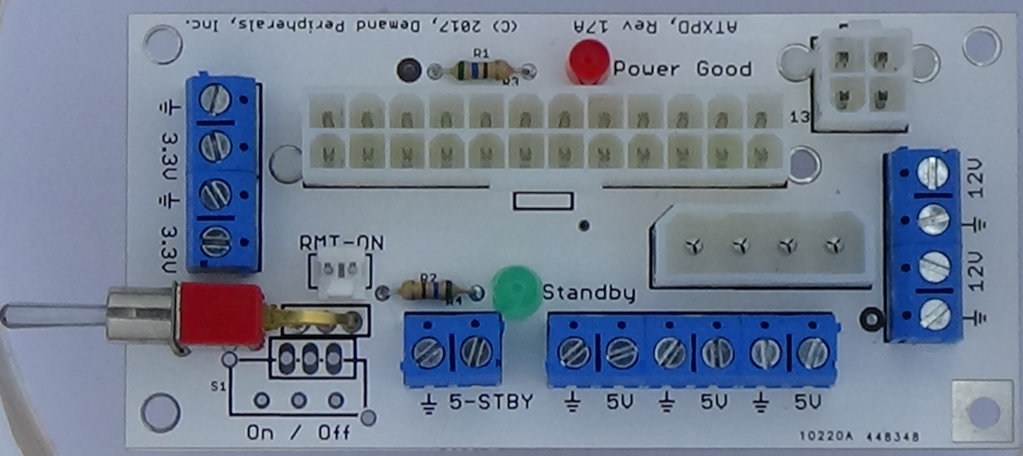 ATX Power Break-Out Card :
Use a surplus ATX power supply in your project by using the ATXPD
break-out card to make the voltages on the ATX supply accessible.
The ATXPD takes in power from the 20-pin/4-pin ATX power connectors
and distributes them out to easy to use screw terminals. There is
an on/off switch and a connector if you want to make the on/off remote
use a real-time clock card for timed on/off.
Click here for more information.
ATX Power Break-Out Card :
Use a surplus ATX power supply in your project by using the ATXPD
break-out card to make the voltages on the ATX supply accessible.
The ATXPD takes in power from the 20-pin/4-pin ATX power connectors
and distributes them out to easy to use screw terminals. There is
an on/off switch and a connector if you want to make the on/off remote
use a real-time clock card for timed on/off.
Click here for more information.
 Molex Power Break-Out Card :
Convert a spare Molex drive connector into a 12 and 5 volt supply
using the DDPD drive break-out card. Easy to use screw terminals
make connecting to the DDPD a snap.
Click here for more information.
Molex Power Break-Out Card :
Convert a spare Molex drive connector into a 12 and 5 volt supply
using the DDPD drive break-out card. Easy to use screw terminals
make connecting to the DDPD a snap.
Click here for more information.
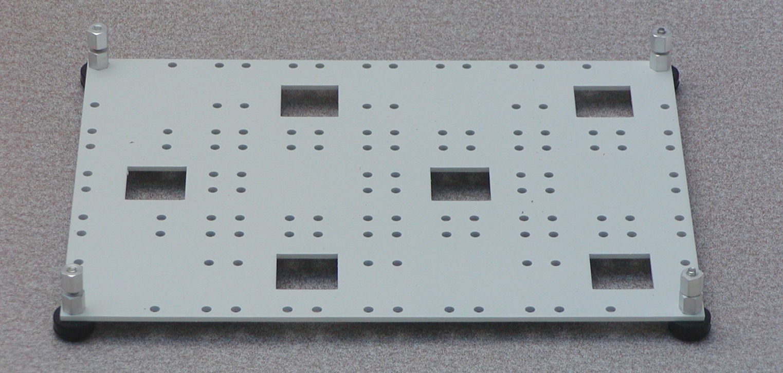 MP43 Aluminum Mounting Plate:
The MP43 makes building a robot or other automation easier by
eliminating the tedium
of drilling mounting holes for Demand Peripherals cards. A top set
of holes can hold up to twelve cards in a four-by-three arrangement
and a second set of holes on the bottom lets you mount another nine
cards on the bottom of the place. Cut-outs make it easy to route
cables from top to bottom. The card is available in unfinished
aluminum or sanded and painted with white primer.
Click here for more information.
MP43 Aluminum Mounting Plate:
The MP43 makes building a robot or other automation easier by
eliminating the tedium
of drilling mounting holes for Demand Peripherals cards. A top set
of holes can hold up to twelve cards in a four-by-three arrangement
and a second set of holes on the bottom lets you mount another nine
cards on the bottom of the place. Cut-outs make it easy to route
cables from top to bottom. The card is available in unfinished
aluminum or sanded and painted with white primer.
Click here for more information.
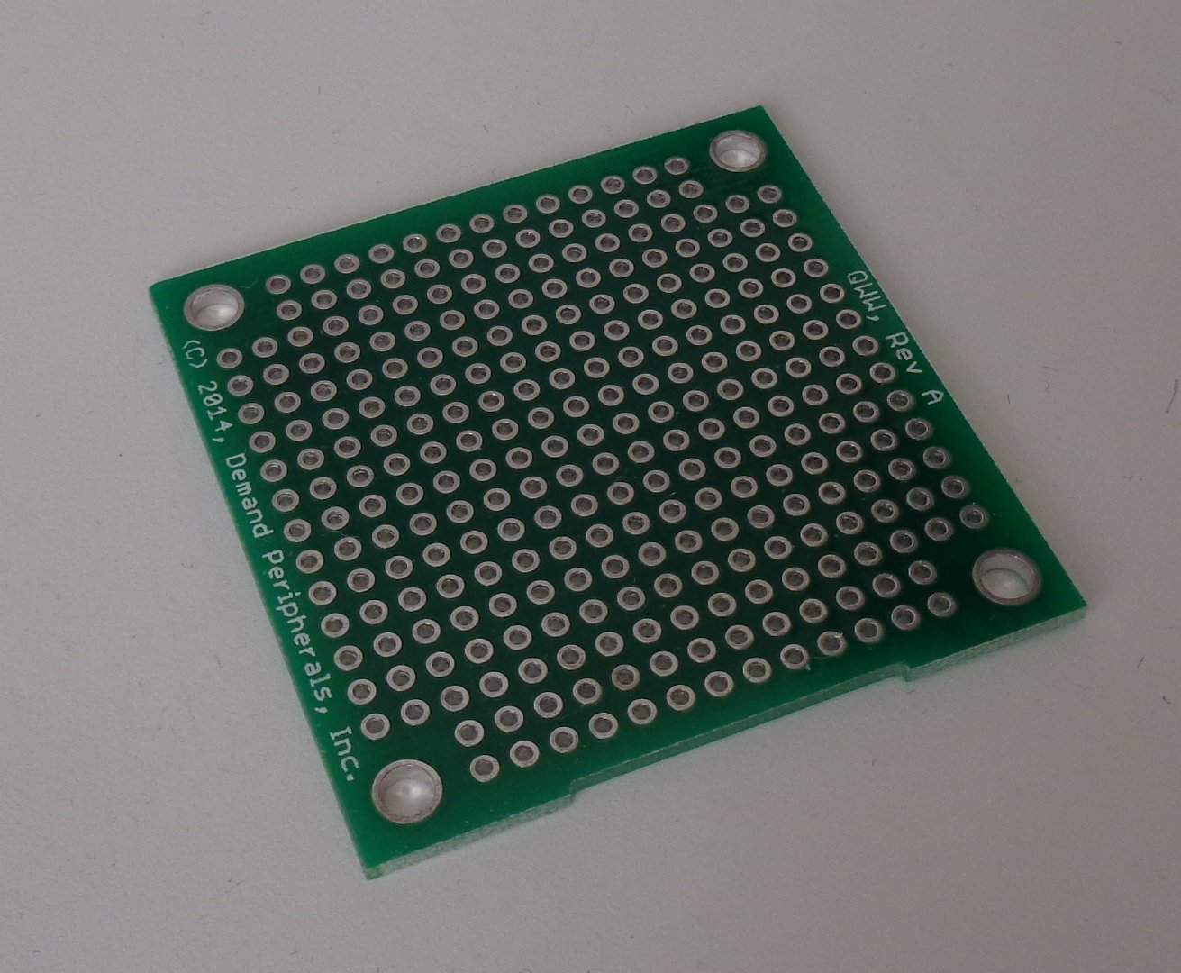
 WW4 Prototyping Card
: The WW4 Prototyping Card is great for building
custom hardware to connect to the BaseBoard4. The card has 1280
plated through holes and is ideal for larger prototypes.
Click here for more information.
WW4 Prototyping Card
: The WW4 Prototyping Card is great for building
custom hardware to connect to the BaseBoard4. The card has 1280
plated through holes and is ideal for larger prototypes.
Click here for more information.
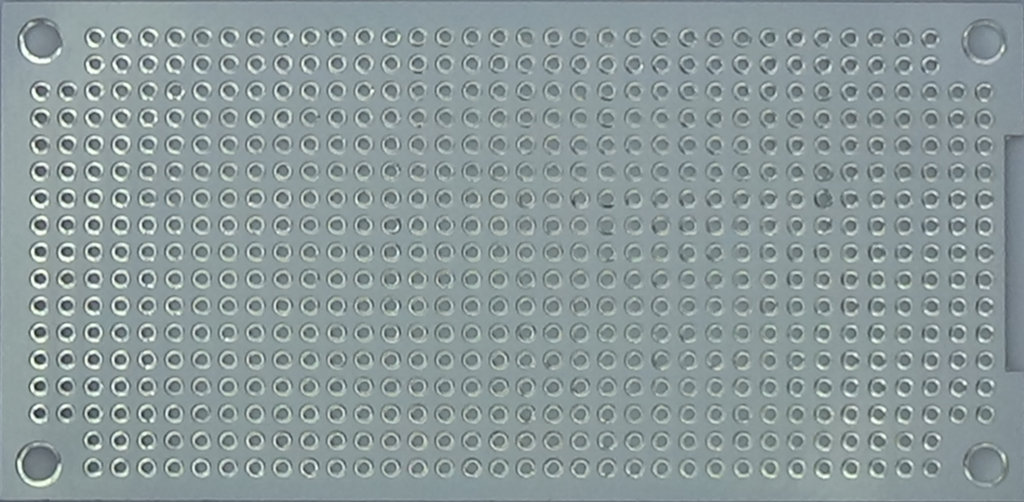 WW2 Prototyping Card
: The WW2 Prototyping Card is great for building
custom hardware to connect to the BaseBoard4. The card has 632
plated through holes and is ideal for most prototyping needs.
Click here for more information.
WW2 Prototyping Card
: The WW2 Prototyping Card is great for building
custom hardware to connect to the BaseBoard4. The card has 632
plated through holes and is ideal for most prototyping needs.
Click here for more information.
 WW1 Small Prototyping Card
: The WW1 Prototyping Card is great for building
custom hardware to connect to the BaseBoard4. The card has 308
plated through holes and is perfect for small circuits.
Click here for more information.
WW1 Small Prototyping Card
: The WW1 Prototyping Card is great for building
custom hardware to connect to the BaseBoard4. The card has 308
plated through holes and is perfect for small circuits.
Click here for more information.
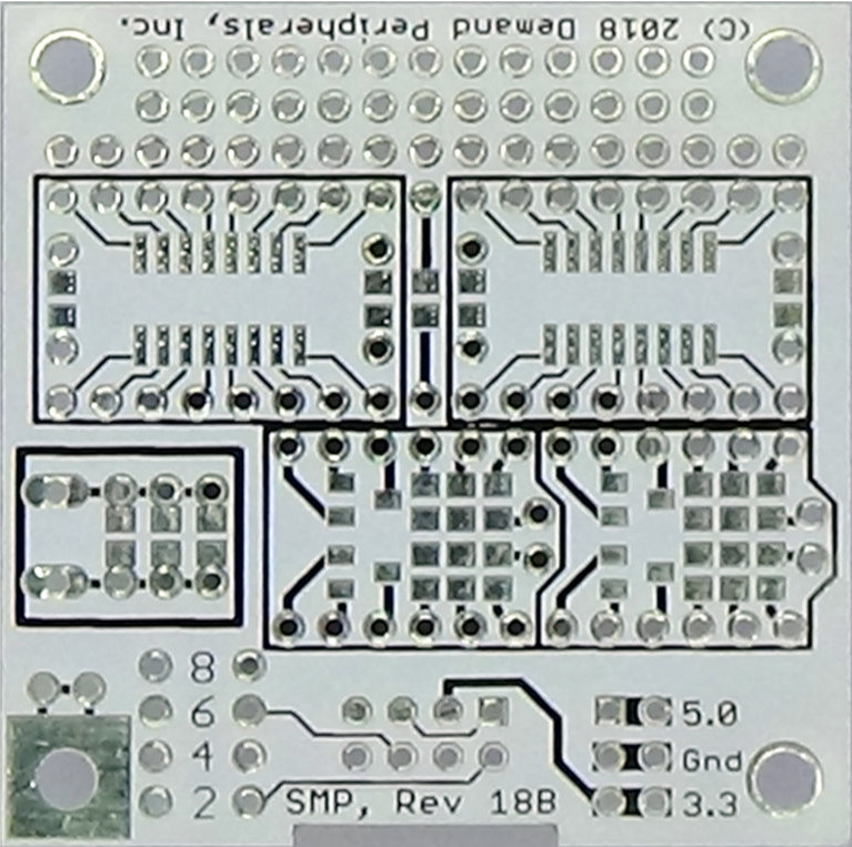 SMD Prototyping Card
: The SMD Prototyping Card makes it easy to build
custom daughter cards. It can hold up to two 16-pin SOP
or TSSOP packages as well as several SOT, 0805, 0603, and
0402 packages. It has space for a connector to go to the
FPGA card. Please see the connector pinout further down
on this page.
SMD Prototyping Card
: The SMD Prototyping Card makes it easy to build
custom daughter cards. It can hold up to two 16-pin SOP
or TSSOP packages as well as several SOT, 0805, 0603, and
0402 packages. It has space for a connector to go to the
FPGA card. Please see the connector pinout further down
on this page.
Click here for more information.
 The Baseboard4 card is 3.8 inches by 3.8 inches. The four mounting holes
are on 3.5 inch centers. Mounting holes have an inner diameter of
0.125 inches. The engineers at Demand Peripherals refer to this as a
"full" size card.
The Baseboard4 card is 3.8 inches by 3.8 inches. The four mounting holes
are on 3.5 inch centers. Mounting holes have an inner diameter of
0.125 inches. The engineers at Demand Peripherals refer to this as a
"full" size card.
 A "half" size card divides a full size card into two while keeping the
3.5 inch mounting hole spacing on the long dimension. A gap of 0.050
inches is left between the cards. This gives the short edge of a half
card a length of 1.875 inches and hole spacing of 1.575 inches.
A "half" size card divides a full size card into two while keeping the
3.5 inch mounting hole spacing on the long dimension. A gap of 0.050
inches is left between the cards. This gives the short edge of a half
card a length of 1.875 inches and hole spacing of 1.575 inches.
 Quarter size cards are 1.975 inches square with 0.125 inch mounting
holes on 1.575 inch centers. Most cards have one mounting hole
connected to ground. You can use this to connect the card to chassis
ground if you wish. The 8-pin shrouded connector for the cable going
to the FPGA card is offset from the edge of the card by about 0.050
inches. A notch is cut into the card near the connector to allow
easier routing of cables under the cards.
Quarter size cards are 1.975 inches square with 0.125 inch mounting
holes on 1.575 inch centers. Most cards have one mounting hole
connected to ground. You can use this to connect the card to chassis
ground if you wish. The 8-pin shrouded connector for the cable going
to the FPGA card is offset from the edge of the card by about 0.050
inches. A notch is cut into the card near the connector to allow
easier routing of cables under the cards.
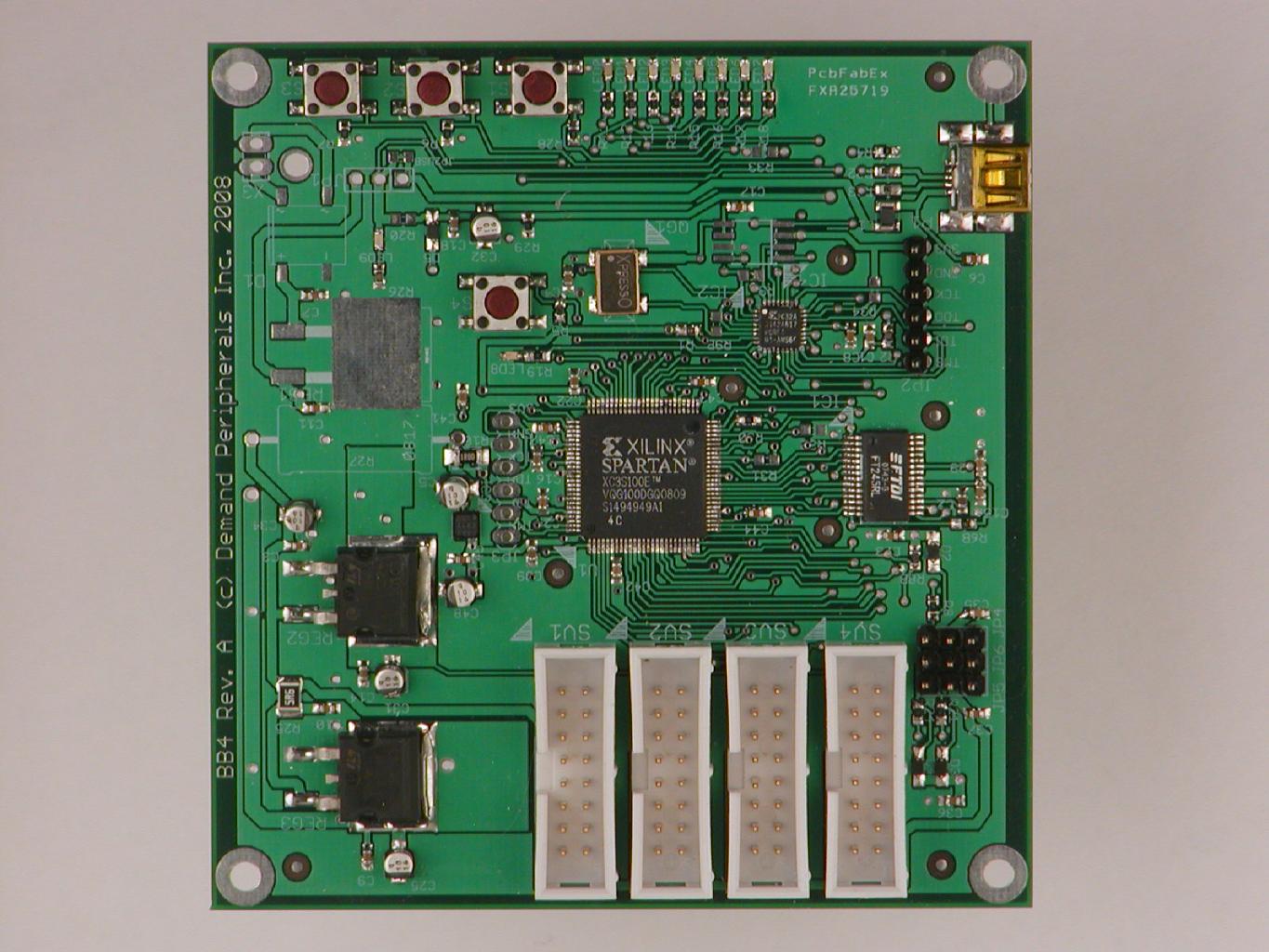
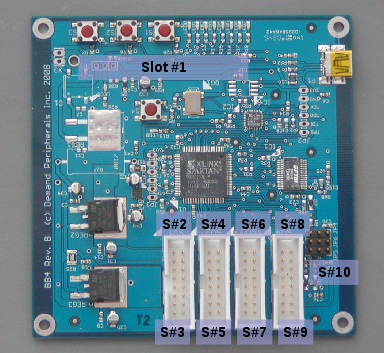 An FPGA can be programmed to implement several different peripherals
simultaneously. Each peripheral is assigned a slot which
defines the set of FPGA I/O pins dedicated to that peripheral. The
photo to the right shows the location of the slots on the Baseboard4.
For example, say you specified an FPGA image (pccore.bin) with a
dual DC motor controller in Slot #2. This means that you should
connect the Dual H-Bridge card to the pins marked S#2 in the photo.
An FPGA can be programmed to implement several different peripherals
simultaneously. Each peripheral is assigned a slot which
defines the set of FPGA I/O pins dedicated to that peripheral. The
photo to the right shows the location of the slots on the Baseboard4.
For example, say you specified an FPGA image (pccore.bin) with a
dual DC motor controller in Slot #2. This means that you should
connect the Dual H-Bridge card to the pins marked S#2 in the photo.