


PULSE2 provides two non-overlapping pulses. The width of each pulse, the offset between them, and the period can all be set with a resolution of 10 ns.
Hardware:
Outputs include both pulses as well as inverted versions
of the pulses. The lowest numbered pin has the uninverted
Pulse 1 output, followed by the P1 inverted output, the
uninverted P2 output and the inverted P2 output. The pulses
are defined by the period, widths, and P1-P2 offset as shown
below.
 p1p:   __|------|_______________________________|------|___
 p1n:   --|______|-------------------------------|______|---
 p2p:   _______________|----|_______________________________
 p2n:   ---------------|____|-------------------------------
With parameters:
 period   |--------------------------------------|
 p1width  |------|
 p2offset        |-----|
 p2width               |----|
The power up default is all pins highs. After the FPGA is loaded pins p1p and p2p go low and p1n and p2n go high.
Resources:
A single configuration resource sets the pulse parameters. All parameters are given in units of nanoseconds, although the hardware actually has steps of 10 ns.
config : period, P1 width, P2 offset, and P2 width in nanoseconds Sanity checks limit the times to less than 10230 ns and to be positive. The period must be greater than the sum of the P1 width, offset, and P2 width. Setting either pulse width to zero turns off that pulse.
Examples:
   # Turn off both outputs (both go low)
   pcset pulse2 config 1000 0 0 0
   # Give a period of 5 us, P1 width of 1 us, offset of
   # 1 us and a P2 width of 500 ns.
   pcset pulse2 config 5000 1000 1000 500
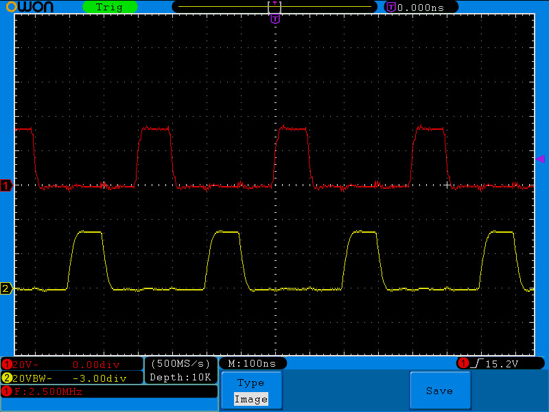
The oscilloscope image below shows the pulses for the command:
pcset pulse2 config 400 100 100 100
Notes:
This peripheral was created at the request of Wes Laquerre and was built to meet his specific requirements.