

 Demand Peripherals
Robotics and Automation Made Easy
Demand Peripherals
Robotics and Automation Made EasyThe IN4 peripheral lets you receive input from four FPGA pins. The pins can be individually configured to send an update when the input value changes.
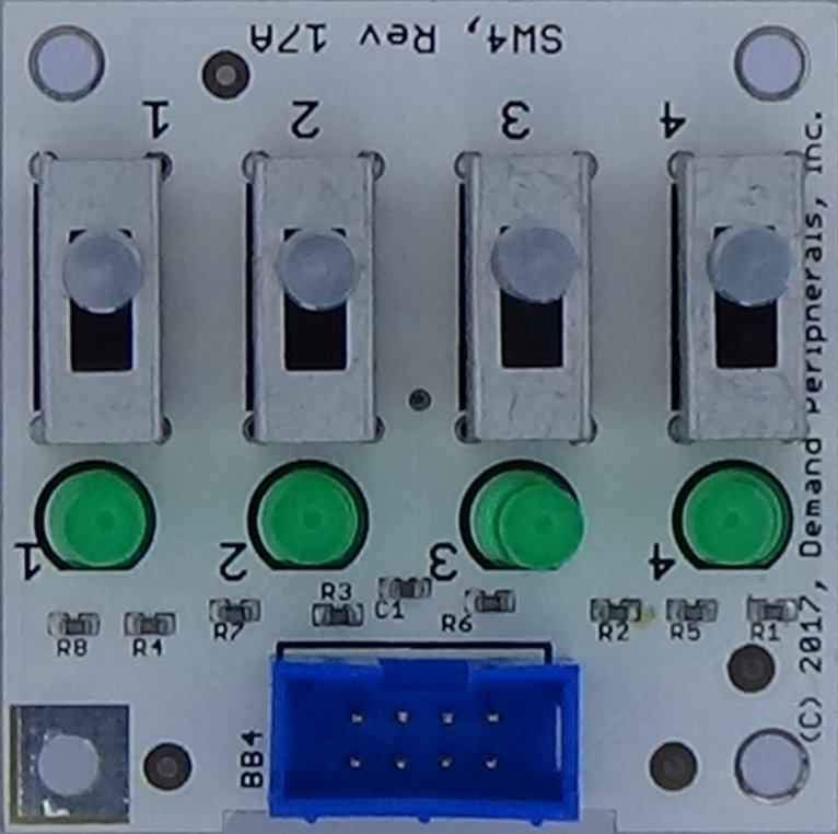
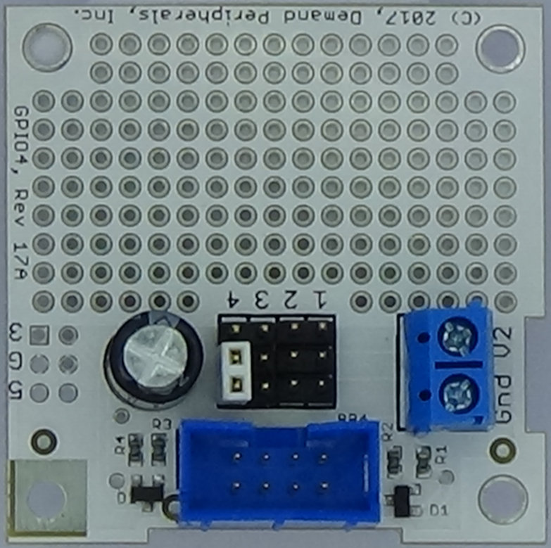
Use either the quad switch card or a GPIO card with the IN4 peripheral.


Hardware:
The IN4 peripheral lets you read or monitor the status of four FPGA pins. Use the SW4 card and IN4 as part of your user interface, or use IN4 and one of the GPIO4 cards to watch for bumper switch closure on your robot. The lowest number pin corresponds to the LSB of the data and interrupt resources.
More information about the SW4 and GPIO4 cards can be found here cards/sw4.html and here cards/gpio4.html.
Resources:
Resources for the in4 peripheral include a read-only data register and a read-write configuration register to determine which pins are monitored for changes.
inputs : the value on the four input FPGA pins. A pcget on this resource returns the current values of all 4 pins. A pcget requires a round trip over the USB-serial link and may take a few milliseconds. Pin values are given as a hexadecimal number with the value of the lowest numbered pin in the LSB.
When used with pccat this resource reports the new value of the pins after one of the monitored pins changes value. Use this resource to wait for changes on the monitored pins.
interrupt : which pins to monitor. A change on a monitored pin causes a packet to be sent to the host. The packet contains the new values of all 4 pins and is made available as a line of pccat output on the 'inputs' resource.
Examples:
To monitor all four pins for changes use the following:
      pcset in4 interrupt f
      pccat in4 inputs