Table of Contents
Motor Control with Raspberry Pi and FPGA
Introduction
This tutorial is for people who are interested in using their Raspberry Pi (RPi) to read the quadrature encoders of two motors. This tutorial provides a quick way to rapidly prototype and test your ideas and data, without the need to program complex microcontrollers. Both the hardware wiring and the software will be explained in detailed.
Purpose and Reasoning
If you use RPi, you will find that the RPi is probably not a good fit to do software decoding of motor quadrature signals. The purpose of the RPi is the high level control of the robot and not to do low level sensor data input and processing, especially for the real-time quadrature signals that are too fast for easy processing on the RPi.
Needed Parts and Wiring Connection
It was not immediately clear to me that Demand Peripherals peripherals and cards were distinct. Peripherals are what is loaded into the FPGA and what your application sees. Cards are circuit boards that attach to the FPGA via ribbon cables. The out4 peripheral makes four FPGA pins outputs and controls their value. The cards that could attach to the out4 peripheral include a quad relay card, a quad open-drain driver, and a general purpose IO card. In my case, I used the dual DC motor controller, dc2, and the dual H-bridge card, the D7HB. It is easy to think they are the same but they are not. The H-bridge card is also use with the bipolar stepper motor controller. Some peripherals work with only only one cards. For example, the lcd6 peripheral only works with the LCD6 card.
For this tutorial, the following parts or devices are used:
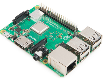
Raspberry Pi
RPi can be purchased from Amazon and many other websites. I will recommend the latest version of RPi to avoid the current limit problems associated with earlier versions of the RPi.
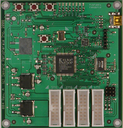
FPGA board
The project does the quadrature decoding of two motors, and we will use an FPGA to measure the quadrature counts and period. This board can actually control up to 8 different devices simultaneously but we will use only 4 devices in this project. The link of the board is at https://demandperipherals.com/cards/baseboard4.html
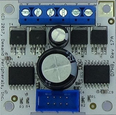
Dual DC Motor controller card
The Linux API and FPGA parts of the motor controllers are described here: https://demandperipherals.com/peripherals/dc2.html. I used the Demand Peripherals dual 7-amp H-bridge card since it interfaces easily to their FPGA card. Other H-bridge cards will work too. The schematics and more information about the D7HB can be found here: https://demandperipherals.com/cards/d7hb.html.
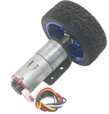
Two motors with quadrature encoders
There are various types of motors encoders out there. You can start with inexpensive ones from Amazon or ebay, such as the ones shown below that have Hall effect gear motor encoders.
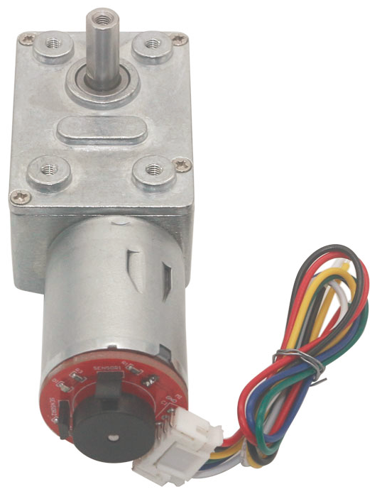
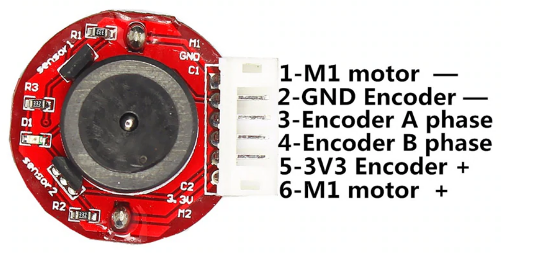
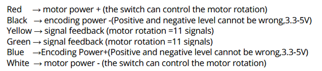
One important thing is to do the wire connections correctly. Below image shows the pin number or the wiring of these types of encoder motors.
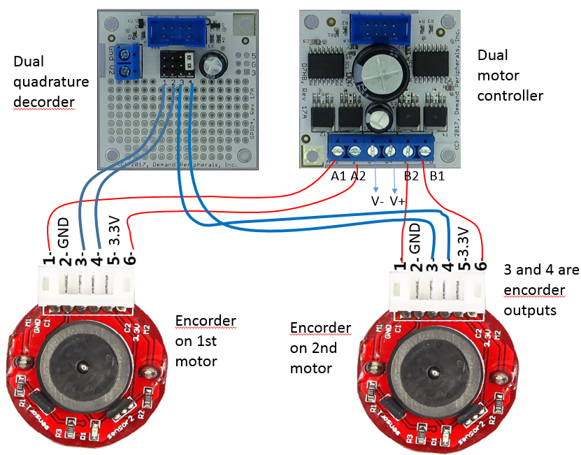
Below image shows the connections of two motor encoders to the DC motor controller card. The A1/A2 and B1/B2 on the DC motor controller card are connected to wire 1 and 6 to drive the motors. The V- and V+ are to the DC power supplier, and I am using a 12V with 6800mAH battery as power supplier. The 2 and 5 are for the powering the encoders which operate at 3.3V. I simply connected RPi’s GND and 3.3V to pin 2 and 5 to power both encoders. The 3 and 4 are the quadrature encoder outputs. With the reading of 3 and 4 from the two encoders, we will be able to determine the moving speed and the distance of the robot.
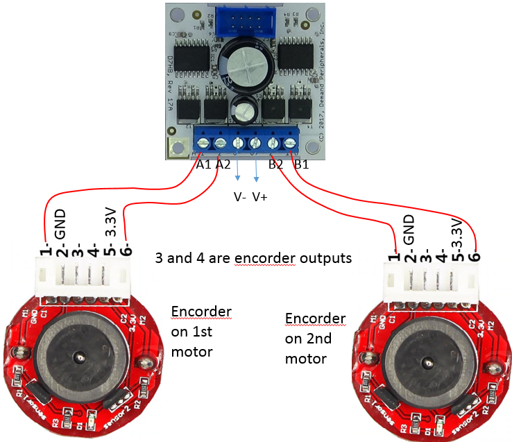
The output of wire 3 and 4 are connected to the FPGA-based dual quadrature decoder to measure the rotation speed and distance
Dual Quadrature Decoder
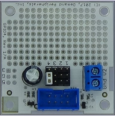
As a continuation from the previous section, let's look at how to connect the motor encoders to the quadrature decoders. I am using the dual quadrature decoder peripheral at this link https://demandperipherals.com/peripherals/quad2.html. This dual quadrature decoder provides two independent channels of quadrature decoding at a maximum frequency of 1 MHz. Since the quadrature signals are at 3.3 volts I could have connected directly to the FPGA card. Instead I used a GPIO4 card to make the wiring a little easier.
Below is the detailed of the wiring. The blue lines connect the pins of 3 and 4 on the encoders to the dual quadrature decoder. For my case, I connect the output of 3 and 4 from 1st motor encoder to pin 1 and 2 on the interface card.
LCD screen
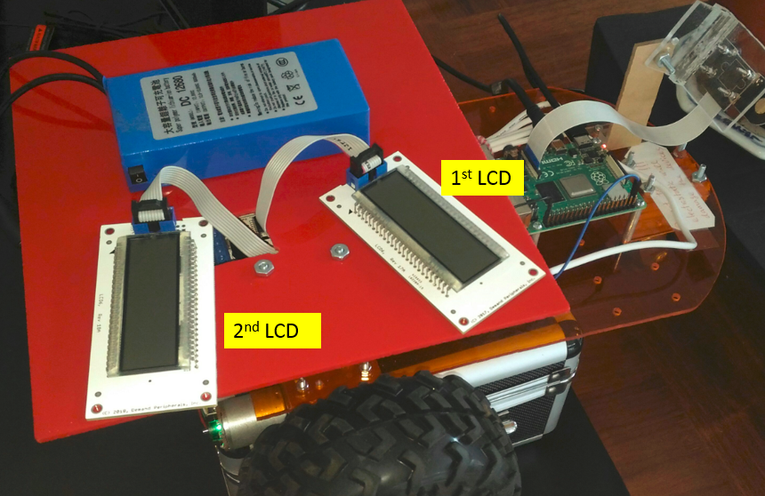
For this project, we will use two LCD displays from this link https://demandperipherals.com/peripherals/lcd6.html to monitor the speed of the two motors.
Connections of all cards and LCD with interface board
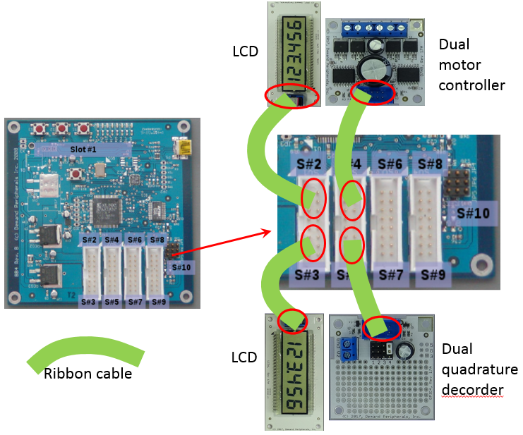
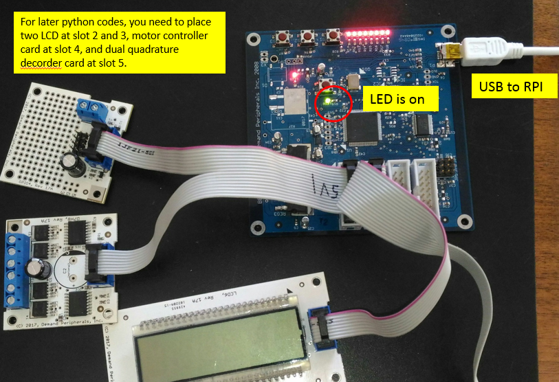
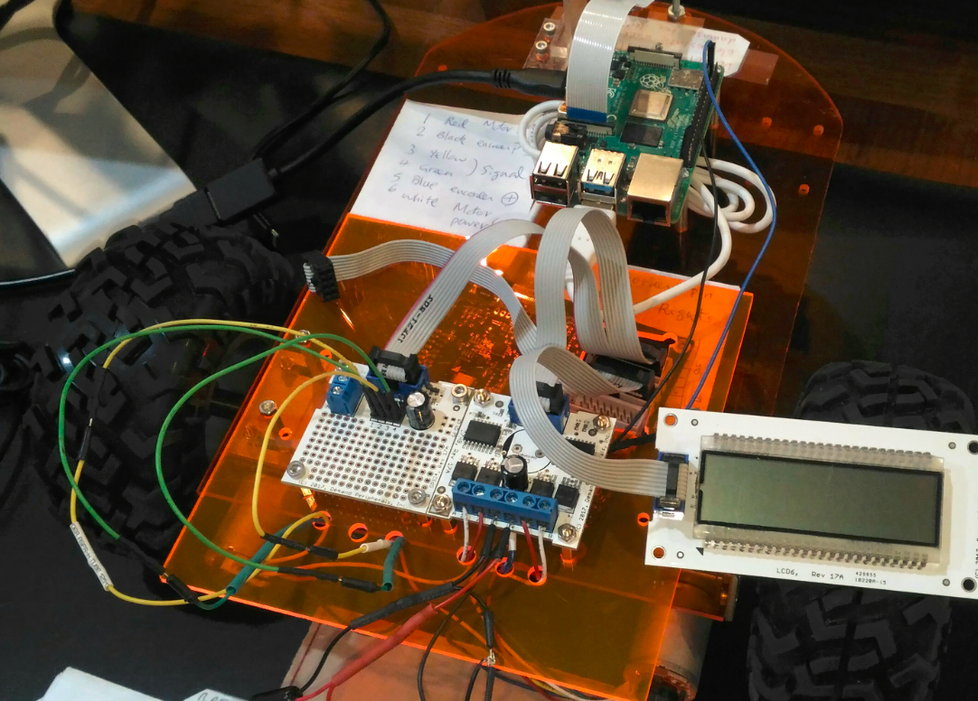
The images below show the connections between the FPGA card, the dual quadrature decoder interface card, the dual H-bridge card, and two LCD displays. The cards can be connected to different slots according to your personal preferences, bur for this tutorial, we will connect the cards and LCDs to the slots as shown below.
Software Operation
In this section, I will talk about the software operation for RPi and all the cards so we can monitor and control the moving of two motors.
Installation of dpdaemon on Raspberry Pi
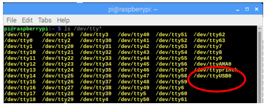
Before the installation of dpdaemon, we need to check the available USB devices on RPi. Do not connect the FPGA board yet. Instead open a terminal, and run the command shown below
ls /dev/tty*
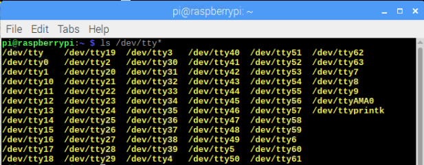
Then we connect the FPGA board with RPi, and run the same command again, and we shall get something like below. With this step, we determine the USB device.
With known USB device, we will install dpdaemon with following commands. The first line “git clone ….” is to clone the repository into the directory “dpdaemon”, then we go into that directory and install program with next four lines.
git clone https://github.com/DemandPeripherals/dpdaemon.git
cd dpdaemon
make
sudo make install
Linux binaries are placed in /usr/local/bin. You may want to add this to your PATH environment variable.
Burning of the images to our cards
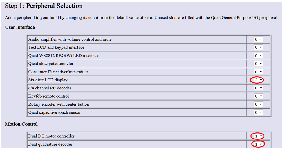
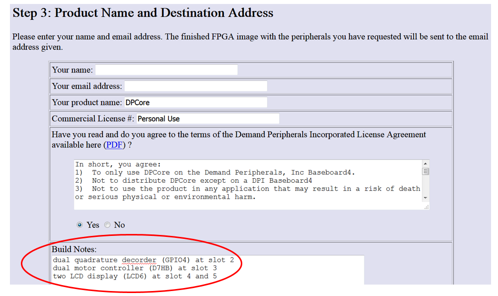
We need load the FPGA image for our peripherals in order to use them. To build an image for the dual motor controller, dual quadrature decoder, and LCD displays, the first step is to go to this link, https://demandperipherals.com/support/build_fpga.html to select the peripherals for our application. For this project, we will select dual quadrature decoder, dual motor controller, and two LCDs, as shown below.
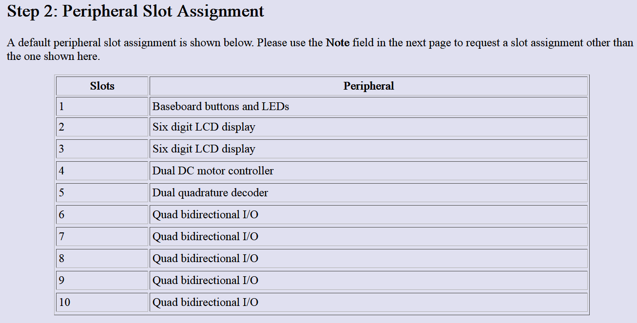
By clicking “continue”, the link will show the second step with some defaulted card devices and slot numbers, as shown below. If you are using the same, you do not need to change, but if you are using different devices on different slots, you can specify them at step 3.
 At this step, we need to input the name and email address, and to specify our choices of peripheral cards and associated slot numbers. Below is only an example, which is not for this tutorial. For this tutorial, we will use the default as step 2.
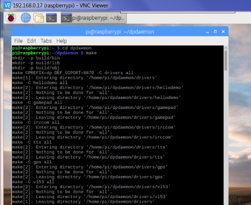
Within a short time, you shall receive the image file “DPcore.bin” from the company, and with the file, we can can download the image to the FPGA card with following commands. You shall be able to see one LED turn green as shown image below.
sudo chmod 666 /dev/ttyUSB0 # where your FPGA connects
stty -F /dev/ttyUSB0 raw # no CR-to-CRLF translation
cat DPCore.bin > /dev/ttyUSB0 # green LED turns on
/usr/local/bin/dpdaemon -ef & # -ef so we see error messages
/usr/local/bin/dplist # list peripherals in the FPGA image
Some photos of my Robot
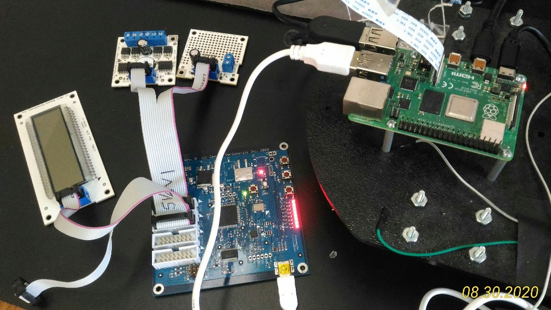
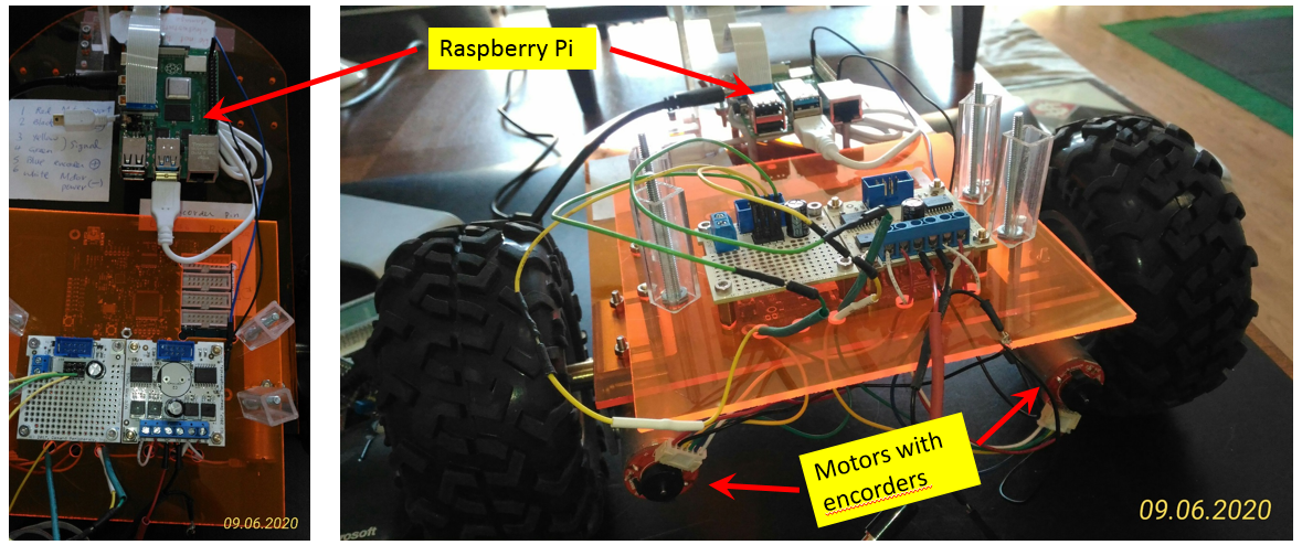
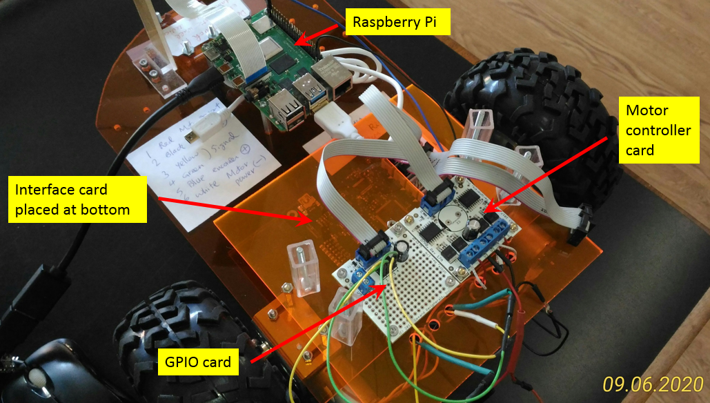
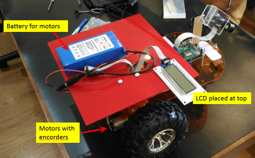
Below are some photos of the robot I assemble. There are quite a few cards and I try to place them nicely without tangling the wires and cables with each other. At the bottom of chassis, I place Raspberry Pi and FPGA card bb4io. A piece of transparent plastic board is then added to accommodate motor controller card and GPIO card. I drilled a big slot on the plastic board for the cable to pass through. After that, I realized the space is too crammed for other stuff, thus a third piece of plastic board, the red color one I found from my garage, is added for the battery and LCD displays.
Simple tests
With everything prepared as previous sections, including all the hardware setup, wiring connections, software installation, and downloading of FPGA image, we are ready to do some simple tests.
Test of FPGA board
With the DPCore.bin image loaded into the FPGA and the green LED lit, you can test everything is working by changing the LEDs on the FPGA card. Try the following commands:
/usr/local/bin/dpset bb4io leds 55
/usr/local/bin/dpset bb4io cc
Test the buttons by starting a stream of button data with the commands:
/usr/local/bin/dpcat bb4io buttons # ^C to exit
Press and release the buttons on the FPGA card. You'll see that the buttons are given values of 1, 2, and 4. Use Ctrl^C to return to the command prompt.
Test of LCD display.
Test the six digit displays with the following commands:
/usr/local/bin/dpset 2 display 1234.56 # display a number
/usr/local/bin/dpget 2 segments # ask which segments are on
/usr/local/bin/dpset 3 display 987.654 # please note we have two LCD on slot 2 and 3
/usr/local/bin/dpget 3 segments # ask which segments are on
Test of dual quadrature encoders and dual motor controller
Start by testing the motors with the following commands:
/usr/local/bin/dpset dc2 mode0 f # motor 0 to forward
/usr/local/bin/dpset dc2 mote1 f # motor 1 to forward
/usr/local/bin/dpset dc2 power0 20 # motor 0 to 20% PWM
/usr/local/bin/dpset dc2 power1 20 # motor1 to 20% PWM
At this point both motors should be spinning. If not, verify that there is power to the V+ and V- terminals. Also verify that the H-bridge card is connect to Slot #4. Once the motors are running you can test the quadrature decoders. Open up another terminals window and in that window enter the following commands:
/usr/local/bin/dpset quad2 update_period 50 # sample period is 50 ms
/usr/local/bin/dpcat quad2 counts # start stream of quadrature counts
A few notes about dc2 and quad2:
- If both control pins for a motor are high, the H-bridge is in brake mode, the power up default.
- If both control pins for a motor are low, the H-bridge is in coast mode.
- The dc2 motor controller has a watchdog timer that shuts off the motors if there is not an update within some specified number of milliseconds. This defaults to off any you have to set the timer value to enable it.
- The quad2 data steam has the count and period for each of the two quadrature decoder. Divide the count by the period to get a fairly accurate estimate of the speed of the motor. This is especially useful when the you have wheel encoders and not motor encoders.
Python Program for Robot Control
I decided to put all above shell commands inside a python code. My original plan is to control all things with a single Python code, including the maneuvering of robot to move, the collection of encodering readings of two motors, and the output of the encoder readings to two LCD screens. Below Python code is still ongoing and it is not yet completed. As for now, the code output two dummy data to two LCD screens, and repeat the forward and reverse each for 5 seconds. I still have following pending works to be finished.
- Solve the issue of “dpcat quad 2 counts”. When I execute this line of command, the shell command keep outputting the “counts” and “timing” of two encoders to terminal screens. I need to figure out a way to output the data to variables inside a python, so I can process the variables inside the python. If I am able to do so, I will be able to control the moving of robot precisely.
- Output the encorder readings to LCD screen. This one is to be done after I solve the issue above.
The links of videos are embedded inside the python code
# one example to use python to control the moving of robot, do this,
# comment out the line "os.system ("dpcat quad2 counts") "
# robot will move forward 5 seconds, then reverse 5 seconds
# https://www.youtube.com/watch?v=7hZcdAOTbUg

# two examples to control the decorder with python, do this,
# keep the line "os.system ("dpcat quad2 counts") "
# and set sample rate 50 (or 20) at the line os.system ("dpset 5 update_period 50")
# https://www.youtube.com/watch?v=teaGGiQSkis
# https://www.youtube.com/watch?v=pTqB3A1N5hY
# you will see robot keeps ouputing counts and times

# to use python to control both robot and encorder
# you need to do some coding


import os
import time

os.system ("sudo chmod 666 /dev/ttyUSB0") # ttyUSB0 is where the FPGA connect
os.system ("stty -F /dev/ttyUSB0 raw") # no CR-to-CRLF translation
os.system ("cat DPCore.bin > /dev/ttyUSB0") # green LED turns on
os.system ("dpdaemon -ef &") # -ef so we see error messages
os.system ("dpset 4 pwm_frequency 20000") # set the motor pwm frequency
os.system ("dpset 5 update_period 50") # set the quadrature decorder sampling rate

while(1):

  os.system ("dpset 2 display 2.22222")
  os.system ("dpset 3 display 3.33333")
  os.system ("dpset 4 mode0 f")
  os.system ("dpset 4 mode1 f")
  os.system ("dpset 4 power0 50")
  os.system ("dpset 4 power1 50")
  os.system ("dpcat quad2 counts") ###
  time.sleep(5)
  os.system ("dpset 4 mode0 b")
  os.system ("dpset 4 mode1 b")
  os.system ("dpset 4 mode0 r")
  os.system ("dpset 4 mode1 r")
  os.system ("dpset 4 power0 50")
  os.system ("dpset 4 power1 50")
  time.sleep(5)
