


The dual quadrature decoder provides two independent channels of quadrature decoding at a maximum frequency of one MHz. The time required to accumulated the pulse counts is also reported so you can get an accurate estimate of the frequency of the input even at low frequency.
Hardware:
The QUAD2 peripheral is often paired with either the GPIO4 card or the GPIO4-ST card.
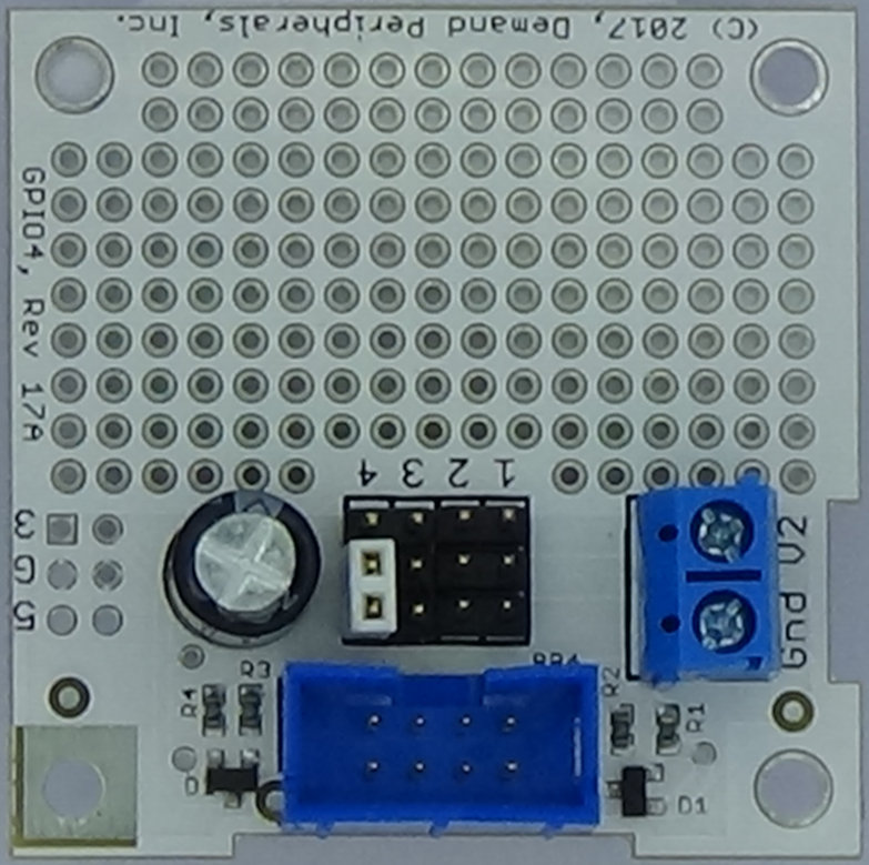
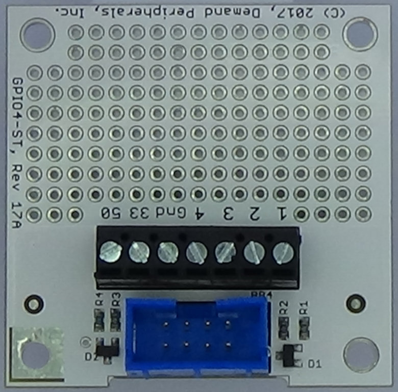
The quadrature inputs are on pins 1 and 2 and on pins 3 and 4. A positive step indicates that the lower numbered input pin (1 or 3) went high before the higher numbered pin (2 or 4). That is, the lowered numbered pin leads the quadrature cycle. The maximum input frequency for the decoder is 1 Megahertz.
The video below reviews quadrature encoding and how to get the most from your quad2 peripheral.
Resources:
The dual quadrature decoder offers a configurable update rate and a select()'able interface to the latest readings.
counts : The quadrature step counts and the number of seconds it took to accumulate those counts. The first number is a signed integer that is the step count and (by the sign) the direction of the first quadrature input. The second number is a float that is the number of seconds it took to accumulate the step count. The third and fourth numbers are the count and accumulation time for the second input channel.
This resource is read-only. You can use the pccat command and select() to get continuous updates into your program.
update_rate : Update period for the counts resource in milliseconds. The pccat command and select() on counts will will give a readable file descriptor every update_rate milliseconds. Setting this to zero turns off all output from the quadrature decoder. The update period must be between 0 and 60 milliseconds in steps of 10 milliseconds. That is, valid values are 0, 10, 20, 30, 40, 50, or 60 milliseconds.
This is a read-write resource and works with pcset and pcget but not pccat.
Examples:
Imagine that the sample rate is 10 milliseconds and that the channel 0 input step rate is about 160 hertz. A sample output from 'counts' might be:
    1   0.007472   0   0.000000
    0   0.000000   0   0.000000
    1   0.007476   0   0.000000
    1   0.007474   0   0.000000
    0   0.000000   0   0.000000
You can not get an accurate frequency from the count alone but by including the accumulation time you can see that the input frequency is about 133.8 Hertz. The accumulation time is measured to the microsecond which usually gives about four digits of accuracy to a frequency estimate.
The output is both frequency and interval based. This is the best of both worlds in that it is accurate for high frequency inputs and equally accurate for very low frequency inputs.