


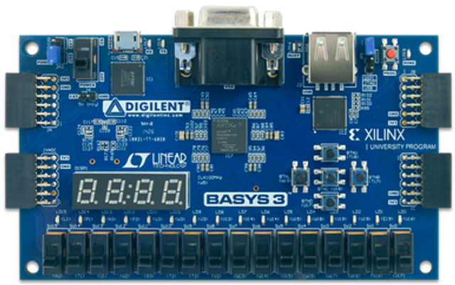
Slot / Pin Assignments
Slot 0: Switches, LEDs, buttons, 7-segment displays
Slot 1: JA top (upper left in picture)
Slot 2: JA bottom
Slot 3: JB top (upper right)
Slot 4: JB bottom
Slot 5: JC top (lower right)
Slot 6: JC bottom
Slot 7: JXADC top (lower left)
Slot 8: JXADC bottom
Host communication is via the on-board USB-serial link.
Slot 0 is already assigned to the input/output devices on the FPGA board.
The API link points to the peripheral's README.txt file
The hardware link points to a schematic of any hardware required by the peripheral.
Please select a peripheral for each slot.