


The QTR4/QTR8 peripherals provide an interface to the Pololu digital QTR sensors.
Hardware:
The qtr4 and qtr8 provides four and eight channels of input from a Pololu QTR-RC sensor. The sensors work by charging a capacitor to Vcc (3.3 volts in our case) and monitoring the capacitor discharge. The discharge rate depends on the amount of IR light reflected off a surface and onto a phototransistor. A sensor is considered light if the capacitor has discharged below the logic 1 level of the FPGA and is considered dark if the voltage is still above the logic 1 level. Sensitivity is controlled by a delay in reading the inputs. The longer the delay, the longer the cap can discharge. Sensitiviy is in units of 10us but since the discharge of a capacitor is exponential the sensitivity is very non-linear. Sensitivity in the range of 5 to 25 seems to work fairly well. Wire each output of the QTR sensor directly to an FPGA pin. Be sure to wire the sensor for 3.3 volt operation.
Resources:
The QTR peripheral lets you select the update period as well as the sensitivity of the sensor. Sensor output is available using pccat.
qtrval : A one or two hex digits followed by a newline to indicate the state of the QTR sensors. A set bit indicated a dark sensor and a cleared bit indicates a lighted sensor.
update_period : Update period for the qtrval resource in tens of milliseconds. That is, the pccat command can select() on qtrval will give a readable file descriptor every update_period milliseconds. Setting this to zero turns off all output from the sensor. The update period must be between 0 and 150 milliseconds in steps of 10 milliseconds. That is, valid values are 0, 10, 20, 30, 40, ... 140, or 150.
sensitivity : The light sensitivity as a number between 1 and 250. Higher values give the sensor capacitor more time od discharge down to a logic 0 level. Sensitivity specified the number of 10 microsecond intervals to wait before reading the sensor outputs. The discharge curve of a capacitor is very non-linear so the sensitivity has no meaningful units of measure.
Examples:
Set the sample rate to 50 milliseconds and the sensitivity to mid-range.
  pcset qtr8 update_period 50
  pcset qtr8 sensitivity 20
  pccat qtr8 qtrval
Hardware Tips:
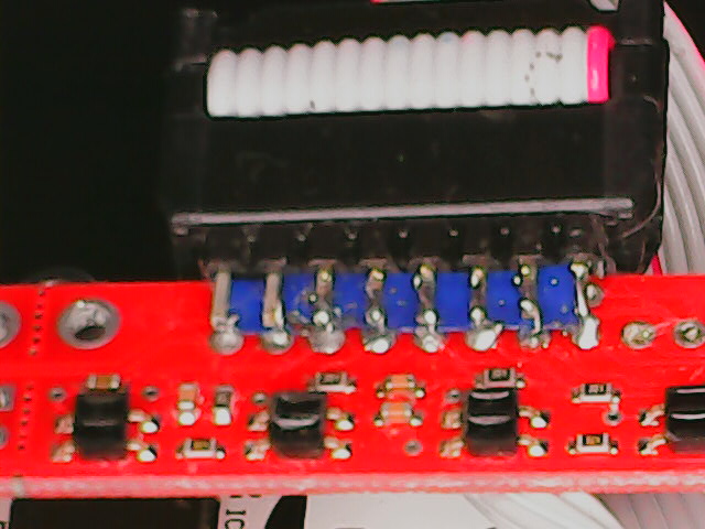
The octal QTR sensor and the BB4 connectors are almost compatible. Of the sixteen pins four are in conflict. If you mount a sixteen pin male header onto the QTR sensor horizontally you may be able to remove the four conflicting pins prior to attaching the connector. The table below shows the four pins in conflict.
| Pin | BB4 | QTR |
|---|---|---|
| 1 | Gnd * | LED |
| 2 | D0 | D0 |
| 3 | V3.3 | Vcc |
| 4 | D1 | D1 |
| 5 | Gnd | Gnd |
| 6 | D2 | D2 |
| 7 | V5.0 * | Gnd |
| 8 | D3 | D3 |
| 9 | Gnd | Gnd |
| 10 | D4 | D4 |
| 11 | V3.3 * | Gnd |
| 12 | D5 | D5 |
| 13 | Gnd | Gnd |
| 14 | D6 | D6 |
| 15 | V5.0 * | Gnd |
| 16 | D7 | D7 |
| * | Remove these pins | |