


The GPIO4 peripheral gives you direct control of four FPGA pins. The pins can be individually configured as inputs or output, and inputs can be configured to send an update when the input value changes.
Hardware:
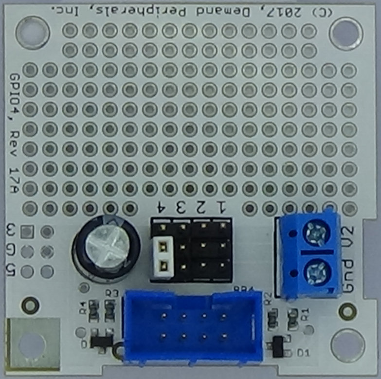
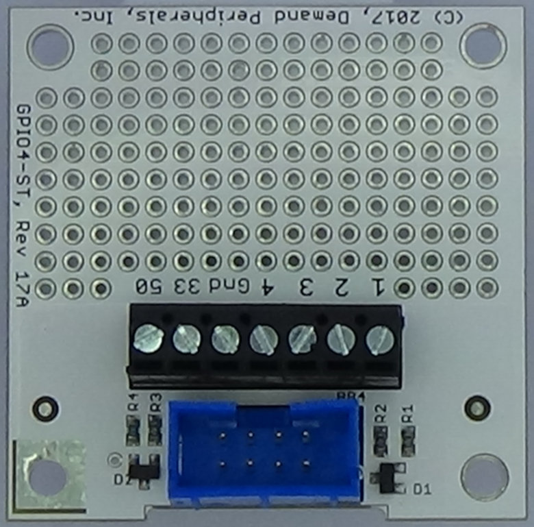
The gpio4 cards give direct access to each of the four pins in a Baseboard slot. Each GPIO pin can be an input or an output, and changes at an input pin can trigger the sending of the pin status up to the host. The highest numbered pin on the connector is controlled by the LSB in the control and data registers. More information about the GPIO4 cards is available here cards/gpio4.html.
Resources:
pins : the value on the GPIO pins.
A write to this resource
sets an output pin, and a read from it returns the current
value on the pins. A read requires a round trip over the
USB-serial link and may take a few milliseconds. Data is
given as a hexadecimal number. You can monitor the pins
using a pccat command. Using pccat only makes sense if one
or more of the pins are configured as input and as a source
of interrupts.
interrupt : an 'interrupt' enable mask. When a pin is an input and the interrupt bit is set for that pin, then when the logic level of the pin changes, the FPGA builds and sends a packet with the new value of the pins. This ability is called 'interrupt' since it is asynchronous and not polled. The interrupt resource works with pcget and pcset.
Examples:
Set pins 3 and 4 to outputs and pins 1 and 2 to input with interrupt-on-change enabled for both. Use pccat to watch for changes at the inputs.
    pcset gpio4 direction c
    pcset gpio4 interrupt 3
    pccat gpio4 pins