


The AVR peripheral lets you control an AVR microcontroller from a Linux application. It lets you program flash memory, program EEPROM, read AVR registers, and read and write RAM locations that you specify in your AVR application.
Hardware:
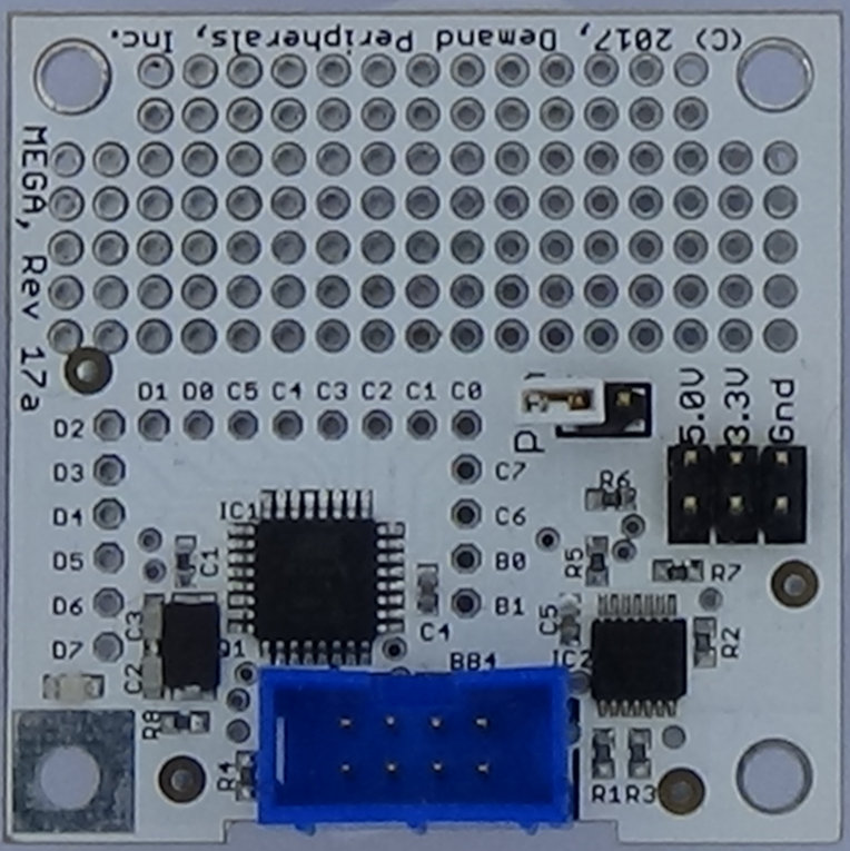
The AVR peripheral requires the MEGA card which has an ATmega88PB AVR microcontroller. More information about the MEGA card is available here cards/mega.html.
Resources:
There are 2 separate categories of resources for this peripheral, programming related and real time data memory access. The programming related resources allow flashing of the program and EEPROM memories. The programming jumper must be installed to use the programming related resources.
The data memory access resources allow you to read and write both RAM and CPU registers while the program is running. Your host application would normally control the AVR application using these resources.
program : read and write program flash
Use this resource to load a program into the AVR or to read the
program that is currently loaded. Be sure the programming jumper is
in place and note that the file path must be fully qualified.
Example:
    pcset avr program /home/me/myavr/led.hex
    pcget avr program /home/me/myavr/ledcheck.hex
eeprom : read and write EEPROM
To flash the EEPROM, specify the beginning address in the EEPROM
followed by the space separate hex values to be flashed. To dump
the EEPROM, specify the beginning address in the EEPROM followed
by the number of bytes to dump. EEPROM addresses range from 0x00
to 0x1ff. Be sure the programming jumper is installed. At most
twelve bytes can be written at one tim. The forms of the commands
are:
    pcset avr eeprom <address> <byte1> <byte2> ...
    pcget avr eeprom <address> <count>
Example:
    pcset avr eeprom 01f2 45 67 89 ab  # write 4 bytes of EEPROM
    pcget avr eeprom 01f2 4            # read 4 bytes of EEPROM
    pcset avr eeprom 0000 77           # set default LED blink rate
vram : read and write specific AVR RAM locations
Use this resource to read and write RAM in the AVR. Mapping
the virtual RAM addresses to physical addresses is done in the SPI
receive character interrupt handler. The sample LED application
maps vram addresses into the 'hostRegs' array of bytes. Please see
the programming section below for an example of AVR RAM location to
virtual RAM mapping. The vram commands are of the form:
    pcset avr vram <address> <byte1> <byte2> ...
    pcget avr vram <address> <count>
Example:
    pcset avr vram 00 77     # set working LED blink rate
    pcset avr vram 01 01     # enable the LED flasher
fifo : read and write to a vram FIFO
Use this resource to write many values to a single RAM location,
i.e. host register, in the AVR. Note that currently there is way
to read many values from a single host register. Also, any one
transaction is limited to 12 bytes of data written to the host
register. The sample fifo application shows the usage of this
resource. Commands are of the form:
pcset avr fifo <address> <byte1> <byte2> ...
Example:
    pcset avr fifo 0 5 6 7 8 9a bc de    # write 7 values to a fifo
                                         # through vram location 0
reg : read and write AVR registers
Use this resource to directly read and write the AVR hardware
registers. Register addresses must be in the range 0x23-0xc6.
Please see the register summary in the data sheet for a list of
the hardware registers. Addresses and data are given in hex and
commands are of the form:
    pcset avr reg <address> <byte1> <byte2> ...
    pcget avr reg <address> <count>
Example:
    pcset avr reg 2b 80    # turn on the LED directly
    pcget avr reg 2a 2     # returns LED port DDR and PORT values
AVR Application Development:
Tools Install gcc for the AVR with the following (for Debian):
sudo apt-get install gcc-avr avr-libc binutils-avr
Code Overview SPI is used for communication between the Linux host and the AVR. Most of the AVR code to support the resources described above is contained in the interrupt handler for SPI chip select transitions and in the interrupt handlers for SPI buffer full and empty. Hooks are provided in these handlers so you can tie your AVR application to SPI packet and byte arrival. A good example to use is the flashing LED application that is pre-loaded onto the AVR.
Development Walk-through Download the pcdaemon source code. Navigate to the LED sample application. Change the timing of the LED flashing.
    git clone https://github.com/DemandPeripherals/pcdaemon.git
    cd pcdaemon/fpga-drivers/avr/Code/samples/led
    vi led.c  # change _delay_ms(1) to _delay_ms(2)
    make
Connect the FPGA card, the MEGA card, and start pcdaemon. While
doing AVR development you may want to keep pcdaemon attached to
your terminal. Print statements in the avr peripheral will give
you more visibility into the programming process. You
can test your setup with a command that changes the blink
rate.
    pcdaemon -ef &
    pcset avr vram 00 11
When run as a daemon (without the -f option) pcdaemon uses root
as its working directory. For this reason you need to give the
full path to your hex file when programming. Install the programming
jumper and load your modified LED program.
pcset avr program /home/me/pcdaemon/fpga-drivers/avr/Code/samples/led/led.hex
You should see messages on the console showing the progress of
the download and verification of the download. When the download
is complete remove the jumper, stop pcdaemon, and power cycle the
MEGA and FPGA cards. The new flash rate should half of what it was
after the previous power-up.
When programming the AVR be sure to remove and reinstall the jumper if it was installed from a previous download. This resets the AVR and is a necessary step in programming it.
Support Getting a Linux host to communicate with an AVR microcontroller might seem a little complex. Please contact us at support@demandperipherals.com if you would like some help with your application.
Demand Peripherals would like to thank Jeff Westerinen for contributing the embedded code for this peripheral. Jeff will receive $2000 for this contribution if the peripheral is used in a commercial license before the end of February, 2023.