

 Demand Peripherals
Robotics and Automation Made Easy
Demand Peripherals
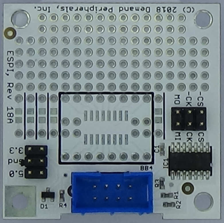
Robotics and Automation Made EasyThe Enhanced SPI Interface card (ESPI) lets you connect any SPI integrated circuit to your robot or other automation. The card has a prototyping area as well as pads for both TSSOP and SSOP surface mount chips.

|
Features: - Easily connects to most SPI chips - Prototyping area as well as TSSOP and SSOP pads - 5 or 3.3 volt compatible - Uses the ESPI 7474 circuit for reliable operation - User space Linux device driver (part of pcdaemon) - Requires one slot on a Baseboard FPGA card |
The ESPI interface card is "enhnaced" in that ringing on the ribbon cable to the card does not affect the SPI clock line. Our 7474 based circuit gives you the ability to use SPI, I2C, or any shift register based device over long runs of ribbon cable. To see how this works consider the timing diagram show below. As long as the D input is stable during the clock pulse, ringing on the clock and data lines is not propagated through to the Q output.
Examine the schematic given below. Notice that the SCK to the chip is the Q output of a 7474 filp-flop. This is why you can connect the ESPI card with a ribbon cable and not have to worry about ringing on the cable affecting the SPI clock line. Of course the ESPI card requires the "espi" FPGA peripheral to generate the timing and signals to the 7474.
This circuit is protected by US Patent Number 10,324,889
Hardware:
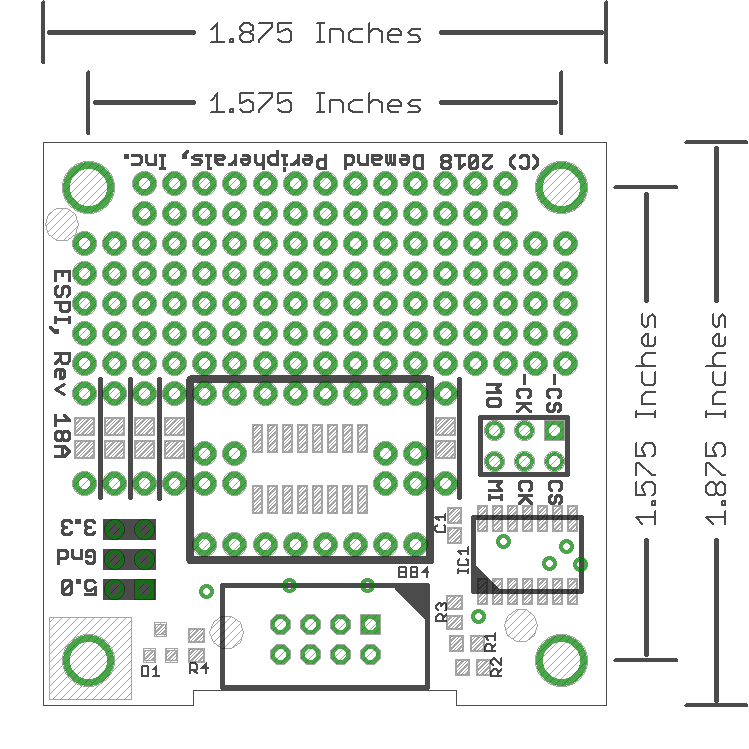
The schematic and layout of the ESPI are shown below. The Eagle schematic and board files are available here: espi.sch and espi.brd. The bill-of-materials is available here: espi.txt.
