This is an old revision of the document!
Table of Contents
Motor Control with Raspberry Pi and FPGA
Introduction
This tutorial is for people who are interested in using their Raspberry Pi (RPi) to read the quadrature encoders of two motors. This tutorial provides a quick way to rapidly prototype and test your ideas and data, without the need to program complex microcontrollers. Both the hardware wiring and the software will be explained in detailed.
Purpose and Reasoning
If you use RPi, you will find that the RPi is probably not a good fit to do software decoding of motor quadrature signals. The purpose of the RPi is the high level control of the robot and not to do low level sensor data input and processing, especially for the real-time quadrature signals that are too fast for easy processing on the RPi.
Needed Parts and Wiring Connection
It was not immediately clear to me that Demand Peripherals peripherals and cards were distinct. Peripherals are what is loaded into the FPGA and what your application sees. Cards are circuit boards that attach to the FPGA via ribbon cables. The out4 peripheral makes four FPGA pins outputs and controls their value. The cards that could attach to the out4 peripheral include a quad relay card, a quad open-drain driver, and a general purpose IO card. In my case, I used the dual DC motor controller, dc2, and the dual H-bridge card, the D7Hb. It is easy to think they are the same but they are not. The H-bridge card is also use with the bipolar stepper motor controller. Some peripherals work with only only one cards. For example, the lcd6 peripheral only works with the LCD6 card.
For this tutorial, the following parts or devices are used:
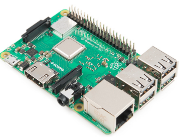
- Raspberry Pi.
RPi can be purchased from Amazon and many other websites. I will recommend the latest version of RPi to avoid the current limit problems associated with earlier versions of the RPi.
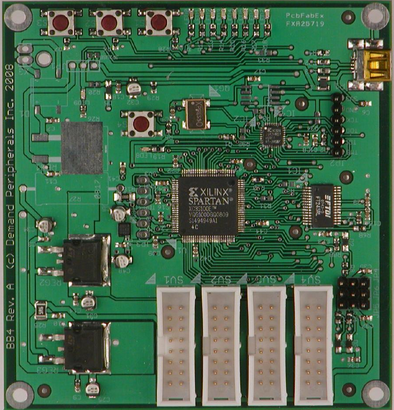
- FPGA board
The project does the quadrature decoding of two motors, and we will use an FPGA to measure the quadrature counts and period. This board can actually control up to 8 different devices simultaneously but we will use only 4 devices in this project. The link of the board is at https://demandperipherals.com/cards/baseboard4.html
- Dual DC Motor controller card
The Linux API and FPGA parts of the motor controllers are described here: https://demandperipherals.com/peripherals/dc2.html. I used the Demand Peripherals dual 7-amp H-bridge card since it interfaces easily to their FPGA card. Other H-bridge cards will work too. The schematics and more information about the D7HB can be found here: https://demandperipherals.com/cards/d7hb.html.
XXXXXX d7hb photo here XXXXXX
- Two motors with quadrature encoders
There are various types of motors encoders out there. You can start with inexpensive ones from Amazon or ebay, such as the ones shown below that have Hall effect gear motor encoders.
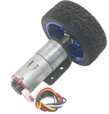
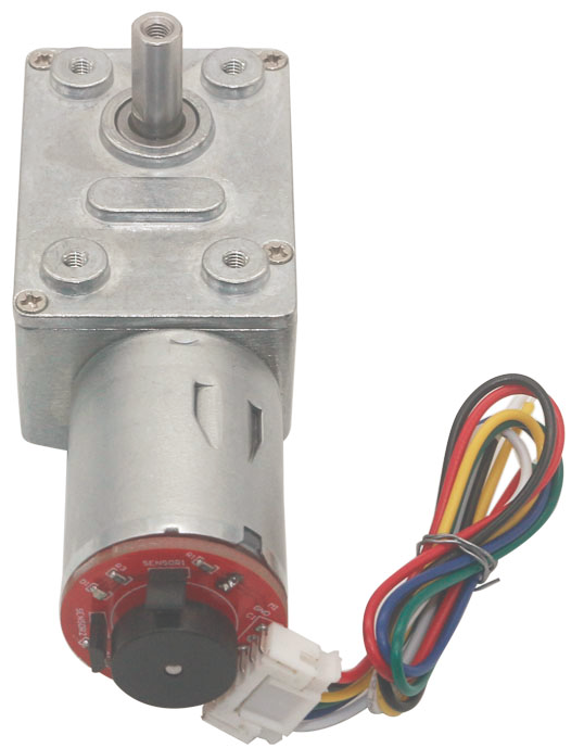
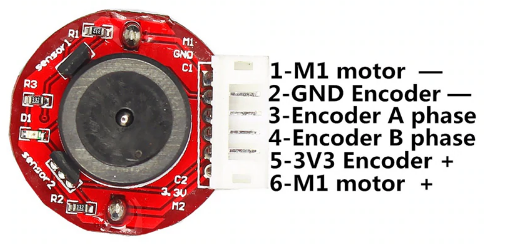
One important thing is to do the wire connections correctly. Below image shows the pin number or the wiring of these types of encoder motors.
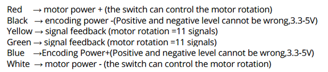
Below image shows the connections of two motor encoders to the DC motor controller card. The A1/A2 and B1/B2 on the DC motor controller card are connected to wire 1 and 6 to drive the motors. The V- and V+ are to the DC power supplier, and I am using a 12V with 6800mAH battery as power supplier. The 2 and 5 are for the powering the encoders which operate at 3.3V. I simply connected RPi’s GND and 3.3V to pin 2 and 5 to power both encoders. The 3 and 4 are the quadrature encoder outputs. With the reading of 3 and 4 from the two encoders, we will be able to determine the moving speed and the distance of the robot.
